Would you like to react to this message? Create an account in a few clicks or log in to continue.
The Dynaco Tube Audio Forum
Dedicated to the restoration and preservation of all original Dynaco tube audio equipment - Customer support for Tubes4hifi VTA tube amp and preamp kits and all Dynakitparts.com products
I've never seen a MK2 like that huge thing next to the other two amps. Unless it has a silk-screened Dynaco logo on it somewhere, it's likely someone built that up from an older MK2 using their own chassis.
tubes4hifi wrote:I've never seen a MK2 like that huge thing next to the other two amps. Unless it has a silk-screened Dynaco logo on it somewhere, it's likely someone built that up from an older MK2 using their own chassis.
I was told that the person who built it intended to create a stereo power amp on one chassis. However, if that is true, I don't know why he split the amp in half, putting components on each end and leaving the middle open. It's a mystery.
I powered up the first amp and ... it didn't power up. The problem? One side of the mains power goes to a terminal on the preamp plug, but there is no connection from that plug back into the Mark II amp. I checked the other two amps and they are wired the same way.
I understand that the Mark II was designed so it could provide power to the preamp, but it appears that the wiring on these requires a preamp connection.
So, what is the recommended course of action? I assume I have to jumper the power, since I won't be using a preamp, and certainly won't be using one through the old plug.
I'll poke around and see if this has been asked before.
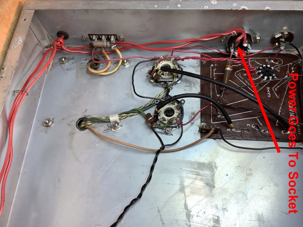
Here's a picture of the odd amp (the other two standard amps are wired the same). As you can see, one side of the line goes to the pre-amp socket, and then the power returns from an adjacent socket lug back to the fuse and the power transformer. It appears to me that all I need to do is wire these two together, but I am now wondering if there are other things that also have to be modified.
OK, I found the section in the build instructions on wiring for preamplifiers. I'll need to re-wire the on/off switch (it is wired to provide power to the preamp even when off); I'll need to jump across the preamp socket in the picture above so the line power can be connected to the transformer.
The big question is what to do about the jumper between lug terminals 2 and 3. Someone else had this question:
johnmeyer wrote:I powered up the first amp and ... it didn't power up. The problem? One side of the mains power goes to a terminal on the preamp plug, but there is no connection from that plug back into the Mark II amp. I checked the other two amps and they are wired the same way.
I understand that the Mark II was designed so it could provide power to the preamp, but it appears that the wiring on these requires a preamp connection.
So, what is the recommended course of action? I assume I have to jumper the power, since I won't be using a preamp, and certainly won't be using one through the old plug.
I'll poke around and see if this has been asked before.
I would redo the power cabling as per the dynaco manual and remove the AC wiring to the preamp connector. It was done in order to let the preamp's power switch control the power to the MkII and thus needed a suitable connected preamp to be present.
peterh wrote:I would redo the power cabling as per the dynaco manual and remove the AC wiring to the preamp connector. It was done in order to let the preamp's power switch control the power to the MkII and thus needed a suitable connected preamp to be present.
John, I don't know what you're looking at for a wiring schematic, or perhaps maybe an 'Assembly Manual' from one of the Mk II / III kits that were out there. But, to the best of my knowledge, these amps were never meant to have a 'remote' turn-on from a pre-amp UNLESS it came in the form of a powered AC plug on the back of the pre-amp that was wired in to the Pre-amp's on/off switch. Even then, the current draw on a pair of Mk IIs or IIIs would have played hell on that pre-amp switch, most likely rendering it 'dead' in a short time! Rather, every one I've ever seen simply had the on/off slider switch mounted on the chassis.....just like on the ST-70. Conversely, I've never seen a ST-35 that had a chassis mounted on/off switch. Most of those DID get their on/off control from a powered AC switch on the pre-amp. BUT, significantly less current draw, so not so much of a problem to the switch contacts.
I don't know where you are on this re-store at this moment, but Pete had some good words of advice when suggesting you simply replace the multi-caps with some new units. That, and the otherwise trouble-prone bias rectifiers, being replaced with a simple 1n4007 diode.
A word about the driver boards: There's some pretty good research out there which supports that the 'stock' Dynaco driver board is about as 'accurate' as anyone can ask for in terms of supplying the needed amplification and inversion to properly run the output stage. So, perhaps before you go spending a lot on 'upgrade' driver boards, consider just using the stock boards initially. HOWEVER, that said, the 'stock' boards DO have to be working properly with component parts in proper spec. Personally I've found that most of these stock boards are usually in decent enough shape to at least bring an otherwise neglected old amp back to life. But, 'coupling caps' are another potential issue, as any DC leakage on these and you can not have 'just' a bias drift problem, but enough leakage and you'll be looking at the death of another output tube as it red-plates itself to destruction. And, coupling caps are CHEAP!! So, my suggestion is that, along with the power supply filter caps and the bias rectifier, I'd also replace the two main coupling caps, or at least test them for DC leakage!!
What you found on the 6AN8 is also pretty typical. I've got a boat load of triode/pentode tubes with one side of the other being either worthless or great! Depending on how and where they saw their original usage (IE TV, Stereo, or other..... ), not unusual for one side to take a beating while the other side remains nearly new!! Sadly, only choice is to replace them! Or, do as Shannon Parks did and redesign a drive stage where the previously incorporated sections get broken out into two dis-similar tubes. In the case of the ST-35, he took the two 7247 tubes and revised the driver to use one 12AX7 and one 12AU7. As there are 'pentode' tubes out there that could match the specs of the pentode section of the 6AN8, one could in theory use two tubes to replace the one. But, I guess that's another whole discussion.
Anyway, I would NOT consider any conversion to Mk III specs until you get a 'stock' MK II working as Dynaco intended. Frankly, the difference between a 50 watt output and a 60 watt output is REALLY slim in general listening conditions. Measurable, yes! Audible? Not so much unless pushed really hard. And, the 'conversion' really does entail a bit more than just re-biasing the amp. To do it properly, there are a few board components that are changes in values (particularly if you have the older spec 'square' MK II boards), plus the addition of a choke, the removal of a PS resistor, and.... to be REALLY correct with it....you need a Mk III output transformer so you can have a 4-ohm output tap. Of course, this isn't necessary if all you have are 8 or 16 ohm speakers. BUT...'technically' if you're going to 'convert' something, then you're either doing it all the way, OR you're just 'modding' something to be 'similar' to something else....or to your own preferance!
Anyway....that's my $0.02 worth! I don't get on this forum too often, but your thread caught my eye as I have a soft-spot for Mk IIs, particularly the older ones. Frankly, I think they're the best sounding amp Dynaco ever made! So, again, treat them well. Consider just 'blue-printing' the driver boards, measuring the spec of each and every component and assuring all the traces are conducting properly. Weak, burned, or damaged traces are another known issue on 'stock' Dynaco driver boards. So, if there's any GOOD reason to replace a board, that's enough of a reason right there!!
Thanks for the confirmation of what I'm now doing. I've posted a lot in this thread, so I'm sure you haven't had time to read it all, but what you suggest is what I'm doing: getting the two stock Mark II amps working, with nothing more than replacing bad tubes and replacing the electrolytic caps. I've already posted several times about why I'm not initially going to replace the selenium rectifier, although I have done that in the past with other amps.
I'm not sure what you mean by "coupling caps" since this is a transformer output amp. Lots of solid state designs use coupling caps to keep the DC voltage out of the speaker. I did replace the 100 uF 50V cap in all three amps (one was completely dead, and the other two didn't test OK). I'm also going to replace the can cap in the two stock amps.
Update
I re-wired the big amp that I'm using as a learning tool, since I have no intention of doing more than just getting it to work. I eliminated all connections to the pre-amp plug and routed the power directly to the transformer, as is shown in the build instructions. I also got rid of the other connections, including the big B+ resistor that goes to that pre-amp plug. (It was 15K instead of the 20K called for in the instructions.) I did this because I don't like having wires radiating energy into space for no good reason, and I also don't want any voltages appearing at that old plug.
I may design and print a cover for that plug, using my 3D printer. It's only five minutes work.
I powered up the unit via my borrowed Variac, while monitoring the AC current. With no tubes, I did get over 100 mA current at full voltage which is a little troubling. However, since I'm not re-capping this unit, I'll live with that. I then powered up slowly with all the tubes installed, but no rectifier. That went well.
For these first two tests, I just used a large 8 ohm resistor across the 8-ohm output.
I then attached a small 8-ohm speaker. I fired it up and heard some buzzing. I then attached a portable CD player and the buzzing went away, so the buzzing was probably just amplification of the un-terminated input.
I then pressed play and got sound!
I had to quit to do other things, but my next step will be to check voltages and adjust the bias, and then attach a "real" speaker (this tiny one was from an old transistor radio, and if it blows up, I don't care).
If all goes well, I'll then re-cap the other two amps, and will also remove the wiring from the pre-amp plugs on both those units.
Tom, I'll try to remember to take a picture of the power switches on those two units. It is pretty odd what the person did when he built it.
This non-stock amp does not have the precision 12-ohm resistor!! It simply has the cathodes running directly to ground. You can see it in the picture in post #29 above. You can see the two driver tubes with the cathodes wired together with a black wire, and then if you look at pin 8 on the socket on the left, it goes down and connects to the ground lug on the speaker output.
I only have an 18-ohm precision resistor, but I have a complete supply of all 5% carbon resistors. With the bias set correctly it will pass 130 ma at 1.56 volts which is 0.2 watts, so I could use a 1/4 watt resistor (1/2 watt would be better). Since I'm simply trying to get this to work, I think I'll do that.
I did check, and the two stock amps are correct.
I wonder how many other strange things are going on with this one?
[edit] Since I have to cut the wire going to ground to insert the resistor, could I instead just insert my ammeter and adjust the bias until I read 130 mA? Would this perhaps produce a better result than having that resistor in the circuit?
[edit2] I couldn't get the bias current to more than 13 mA. Also, I tested the 465V voltage and it measures 595 volts. Hmmm.
John, the 'coupling caps' are the two 'big' caps located on the driver board. They connect the two sides of the phase inverter output to the two input grids of the 'output' tubes. They pass AC signal, but 'block' DC, so many people refer to them as 'blocking' caps. But, as they 'couple' the phase inverter side of the driver section to the output tubes, the term 'coupling caps' is pretty standard.
I'm giving up on this very non-standard "Mark II." I'm putting that name in quotes because I'm suspecting that perhaps this doesn't even use the standard Dynaco transformers (I can't find a nameplate, so I don't know). How else could I be getting a B+ of just under 600 volts? Fortunately, the non-standard caps the builder installed are rated to 600WVDC.
I guess I should check the transformer wiring to make sure the builder didn't use the wrong taps.
I did try the bias one more time, with the Variac turned WAY down to get a normal 465V B+. I put two 1/4 watt resistors in parallel to give me 1/2 watt dissipation (22 and 27 ohm in parallel = 12.1 ohm). I still couldn't get the bias even close to the right numbers.
John, just a quick word here: Measuring voltages in an amp is usually done while in 'operating' condition. So, if you're measuring things WITHOUT the power tubes in place, you're certainly going to get some excessive readings! Basically the things you can measure without the power tubes are the filament voltage, any bias voltage tap reading, and the HV tap voltage. All these should fall within a range that is consistent for an 'unloaded' amp. Once you install the power tubes you should be doing so with the amp on a dummy load. Then, you need to check to see if you are in the proper operating range for bias quiescent current. At that point you can check the B+ voltage going to the output transformer, as well as the voltages at the plate and screen. Again, those should be within 20 volts or so of what is on the schematic voltage chart or listed at the tube pins on the schematic. Figure some increase is typical as household AC is now generally a bit higher........so this translates into significant raise in HV as well as also possibly in the filament windings; both 6 volt and 5 volt (for the rectifier). Generally speaking, these are not so high as to be prohibitive....but some times some transformers can get pretty out-of-line with these levels. In those cases, compensation may be necessary. But, assuming you're MkIIs are consistent with most out there, you should be in the ball park.
As to the iron itself, both the output and power transformer should have part numbers on them. These are easily comparable to Dynaco's OEM part numbers. The power transformers on Mk IIs and Mk IIIs are both the same, and I think P-782 is the power transformer Part number. The Output Transformers differ as previously stated by the addition of the third 4 ohm secondary tap on the Mk III OT. I believe the Mk II was an A-430 where the Mk III is an A-431.
Anyway, as to the bias, you should be looking for a voltage here, not a 'current' level. On the 'out' side of the bias rectifier you should be seeing a 'negative' (relatively speaking) bias voltage of some where around -45 to -50 volts as I recall. I just did a quick search and couldn't find a spec on it, but I believe it takes about that to feed the bias adjustment network and end up with the correct bias current draw on the tubes. To that, if you do the math on the Mk III using KT88 output tubes, the Dynaco Schematic for a Mark III shows the bias sensing resistor as being 11.2 ohms, with a voltage across it of 1.56 volts. That works out to 139ma for both tubes, or 70 ma each. Rather hot imho, but I didn't design the thing!! The Mk II shows a 12 ohm bias sensing resistor with 1.56 volts across it.....or 130 ma for both tubes, or 65ma each.
Anyway, you need to have a bias supply with a negative voltage feeding the input grids of both output tubes through the 100K input grid resistors (ahead of the 1K 'stopper' resistors) such that when adjusted at appx the mid-point on the bias adjustment pot, the voltage across the 12 ohm bias sensing resistor is roughly 1.56 volts. So, check to make sure there IS a 12 ohm resistor in place, then check to make sure it's measuring 12 ohms, and finally, make sure you've got a good negative 40 volts or so at the eyelet 2 on the driver board. BTW, you can also do a test with the rectifier tube removed where you actually put your DVM probe on the socket pin of each output tube on the input grid pin 5 and see if you have a good negative voltage coming in. If the rectifier is NOT in place, you're safe from a HV perspective, but make sure the PS filter caps are discharged prior to doing this!!!
Anyway, don't give up on the odd-ball amp yet. It's a good learning platform! Tom D.
BTW, 'spec' on the bias sensing resistor is 1 watt...... so if you're trying to fabricate an equivalent 12 ohm resistor to replace the 'stock' bias resistor, you need to be doubling up again to get to the 1 watt level!!
Wharfcreek wrote:John, the 'coupling caps' are the two 'big' caps located on the driver board. They connect the two sides of the phase inverter output to the two input grids of the 'output' tubes. They pass AC signal, but 'block' DC, so many people refer to them as 'blocking' caps. But, as they 'couple' the phase inverter side of the driver section to the output tubes, the term 'coupling caps' is pretty standard.
Ah yes, I see them. They are part of the quad-cap can, 20uF each. You are right: "coupling caps" is the correct terminology and they are used the same way in solid state design. I should have seen those in the diagram. Thanks for pointing that out.
Wharfcreek wrote:BTW, 'spec' on the bias sensing resistor is 1 watt...... so if you're trying to fabricate an equivalent 12 ohm resistor to replace the 'stock' bias resistor, you need to be doubling up again to get to the 1 watt level!!
I didn't know the spec, but according to the manual, the resistor when properly biased is supposed to pass 130 mA at 1.56 volts. Power = Volts * Amps. As I posted above, if you multiply those together it comes to 0.2 watts. So, in theory, a 1/4 watt resistor would work, but I de-rated that by 2 and used a 1/2 watt resistor by putting two 1/4 watt resistors in parallel to give me 12.1 ohms with the ability to handle up to 1/2 watt.
It doesn't much matter now, since I've given up on this very non-standard amp and am concentrating instead on the two stock amps.
Wharfcreek wrote:John, just a quick word here: Measuring voltages in an amp is usually done while in 'operating' condition. So, if you're measuring things WITHOUT the power tubes in place, you're certainly going to get some excessive readings!
I did initially power up, through the Variac, without tubes, in order to both test and "form" the capacitors. I then powered up with tubes, but no rectifier, following the advice given in this forum, and elsewhere. I slowly powered up a third time, with everything installed and it was only at that point I started making measurements and found everything out of whack.
Wharfcreek wrote:Once you install the power tubes you should be doing so with the amp on a dummy load. Then, you need to check to see if you are in the proper operating range for bias quiescent current. At that point you can check the B+ voltage going to the output transformer, as well as the voltages at the plate and screen. Again, those should be within 20 volts or so of what is on the schematic voltage chart or listed at the tube pins on the schematic.
Yup, that's what I did, using a 5W 8 ohm resistor across the output. I then powered down and used a small 8 ohm speaker instead. I was able to get audio, but it wasn't great, and it was then that I started measuring voltages.
Wharfcreek wrote:Figure some increase is typical as household AC is now generally a bit higher........so this translates into significant raise in HV as well as also possibly in the filament windings; both 6 volt and 5 volt (for the rectifier). Generally speaking, these are not so high as to be prohibitive....but some times some transformers can get pretty out-of-line with these levels.
Yes, I've seen the discussions about how the Dynaco was designed for 115-117 volts and line voltages today are often well in excess of 120 volts. I did some simple repair work at a cottage in Carmel yesterday and the line voltage, according the UPS front panel, was hitting 125 volts at times.
Even that 125/115 would not explain getting 595 volts B+ instead of the 465 shown on the schematic.
Wharfcreek wrote:As to the iron itself, both the output and power transformer should have part numbers on them.
Nope, not a mark. That, coupled with the non-standard chassis you see in that picture I posted in the picture forum, is what makes me believe that someone may have just attempted to duplicate the Mark II using parts he found lying around. The other two amps I'm about to get working were built back in the 1950s by the guy who asked me to restore them, so I know they use stock parts. I also know that, at one time, they worked.
Wharfcreek wrote:Anyway, as to the bias, you should be looking for a voltage here, not a 'current' level.
Yes, that is how you measure it, but if you read the manual it says, "The correct setting of the bias provides a total cathode current of the EL-34 tubes of 130mA. This current through the precision 12 ohm resistor produces a voltage drop of exactly 1.56 volts DC ..."To me, this sounds like what the designer was really trying to do was to ensure a 130mA current and since current measurements cannot be done without removing a wire and inserting an ammeter, the old-fashioned solution was to use a small resistor that wouldn't induce much voltage, and measure across it (hence the need for a vacuum tube volt meter instead of your trusty Simpson 260, with its relatively low input impedance). Since I had cut the wire in anticipation of inserting a 12 ohm resistor, I just measure the current. I then wondered out loud in my post above whether biasing this way and not re-inserting the 12-ohm resistor might actually provide a little better performance.
I'll never know, since this non-stock amp is not worth saving, and I'm not going to do anything non-standard on the remaining two stock amps.
Wharfcreek wrote: ... and finally, make sure you've got a good negative 40 volts or so at the eyelet 2 on the driver board. BTW, you can also do a test with the rectifier tube removed where you actually put your DVM probe on the socket pin of each output tube on the input grid pin 5 and see if you have a good negative voltage coming in. If the rectifier is NOT in place, you're safe from a HV perspective, but make sure the PS filter caps are discharged prior to doing this!!!
Thank you for that advice. It is very helpful to have more tips on where to test and what to expect.
Wharfcreek wrote: Anyway, don't give up on the odd-ball amp yet. It's a good learning platform! Tom D.
I may go back to it a few more times, but I have half a dozen other projects, and the goal is to finish.
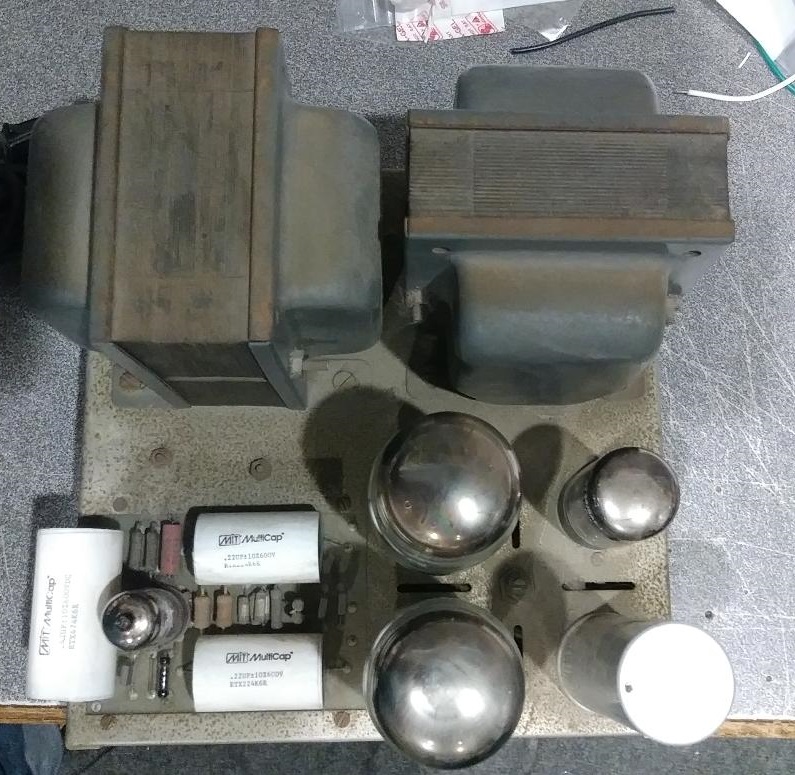
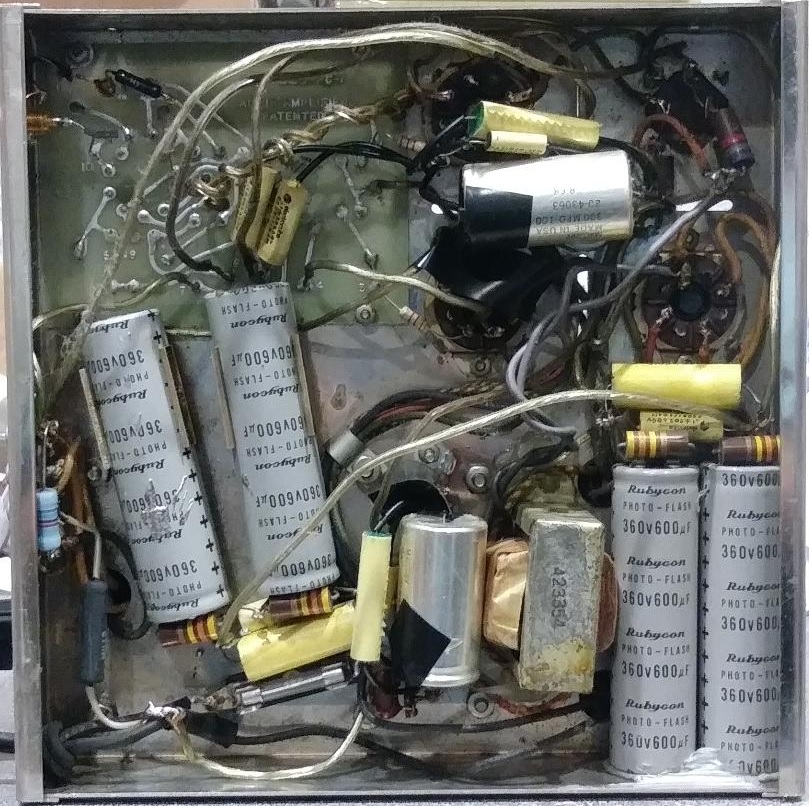
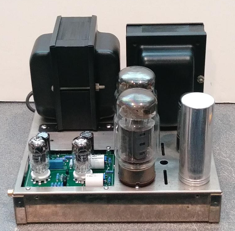
tubes4hifi wrote:BTW, here's some photos of a MK3 I rebuilt just last month . . . 3 before photos, 3 after photos
Rebuild?? It looks like you used all new parts. Are those the original transformers? If so, you did a remarkable job cleaning them up and, I assume, re-painting them. As for the chassis, how did you clean it? I've tried various things on the removable bottom plate, but even a buffing wheel didn't produce a very good result.
I'll decide how much cosmetic work to do once I've got it working. My friend who owns these has a very nice set of McIntosh tube amps with the chrome and glitter, so he's already got that "tube cachet" covered. Since these will be operated with the cover in place, the only thing I might do, at the very end, is to spray paint the cover.
Did you spray paint those transformers and, if so, what sort of paint did you use? I don't want to get too exotic by using something like a two-part epoxy paint, but I would like to use something that won't peel or smell when it gets pretty warm.
John, I just wrote a prior response, but it got 'deleted' by the system, so this one is going to be a LOT less in content. Basically, 'no', the coupling caps are NOT part of the quad cap. If you look at the pics of tubes4hifi's amp, in the first one you'll see three large caps on the driver board, two of which are running laterally and point toward the two output tubes. THOSE are the coupling caps! And, while they can be purchase as high-dollar 'audiophile' items, they can also be purchased as just plain 'parts'! A couple of yellow poly-caps of the correct value are only about $1.50 each, and as they are 'cheap' insurance against a potential leakage problem with the OE coupling caps, particularly on an amp as old as a Dynaco MkII!!
I've read your responses in your last two posts, and I think you're on the right track. Were it me, I'd concentrate on the 'non-Dynaco' amp until I got it working. I know that would teach me a lot about what to look for in the OE Dynaco products. After I got my 'schooling', I'd progress to the factory amps. But, that's just me! That project would become a 'study' of the schematic, the values, the circuits, and proper working relationships between the different sections of the amp, ie power supply, bias circuit, voltage driver, phase inverter, and final output. Rather than seeing the amp as a whole, you begin to see it in 'sections'......and as each section becomes an individual project for detailing out, the 'whole' just comes together as an operating unit. Needless to say. 'tweaking' is also part of this! But, once you understand the function of each component in each section, the whole unit becomes a LOT more 'simple' to figure out!!
Good luck!
Tubes4hifi:....Nice job on that MkIII! Old 'vintage' Tung Sol 6550s in that thing? Tom D.
Wharfcreek wrote:Basically, 'no', the coupling caps are NOT part of the quad cap. If you look at the pics of tubes4hifi's amp, in the first one you'll see three large caps on the driver board, two of which are running laterally and point toward the two output tubes. THOSE are the coupling caps!
Oops, my bad. The others are just filtering. Good advice about replacing those with polypropylene caps. I have some lying around. I think some are 0.22 uF. Not sure about the voltage without going through the parts bin.
Wharfcreek wrote:I've read your responses in your last two posts, and I think you're on the right track. Were it me, I'd concentrate on the 'non-Dynaco' amp until I got it working.
That is why I started with it, but as I've said, the super-high voltage has me convinced that there is a lot of non-standard stuff in this, and I have no assurance that the non-standard build ever worked. If I really kept with it until it worked, not only would I probably kill several days, but I don't think I'd know much more than I know now. I've gotten a pretty good "schooling" with what I've done so far, although I'll never know as much about tubes as I do about solid state.
My goal in every project I tackle is to finish, and that's what I intend to do here, so I'm proceeding today, if time permits, with the first of the two stock amps (although one of them has a choke the size of the two stock transformers which someone added to the power supply).
Speaking of finishing, I need to first bench test a photo eye used to center a four foot belt on an industrial belt sander, used to finish large "live edge" table tops. All the electronics are potted, so I can't do component level repair, but I need to see if the intermittent operation can be fixed. The guy's business is stalled out until it gets fixed. Tall order ...
very basic cleaning, green scotchbrite pad (same thing used on the back side of most kitchen sponges). The only new parts were the driver board and the tube sockets (as they were pretty wasted), so under $100 in parts. Quick & EZ painting of the transformers, didn't even need to remove them from the chassis, just blue painters tape to keep paint off the chassis.
tubes4hifi wrote:very basic cleaning, green scotchbrite pad (same thing used on the back side of most kitchen sponges). The only new parts were the driver board and the tube sockets (as they were pretty wasted), so under $100 in parts. Quick & EZ painting of the transformers, didn't even need to remove them from the chassis, just blue painters tape to keep paint off the chassis.
I've rebuilt both Dyna Mk2s and MK3s, usually with a lot of mods. It appears you have at least one genuine MK2, possibly a MK-3 (you can tell by opening up and seeing if there is a choke (MK3) or a resistor (MK2) between the 1st and 2nd cap sections. I see vent slots on one chassis which may be a MK3. Or look at the output connections, an 8/16 ohm output for a MK2, 4/8/16 ohm output for a MK3.
First of all, at least one output tube is shot, I see the white top indicating air has leaked in. I can't tell if the rectifiers are 5U4GBs (MK2) or 5AR4s (MK3) so that would be another hint as to unit type, however, they may have been switched so I wouldn't depend on that for identification. You'll probably need all new tubes. I like Jim McShane (google jim mcshane tubes to get his site) as a tube vendor.
I won't comment on those mentioning replacing the driver boards, there are many options for doing that. If repairing the existing boards, be very careful and use as low a wattage soldering iron as possible to replace parts so you don't lift the traces on the existing boards.
Based on the experiences with MK2/3s and having rebuilt a number of Dyna ST-70s, I'll offer the following recommendations:
1.) Replace the power supply cap can. Its either leaking or is shot. I have used the 40/80/30/20 from DynaKit Parts, I recommend that highly at it is 550 volt rated which you really need in this day of 122 volt AC or higher household voltage. The transformer output is roughly 4 times the input and the original transformer input was rated for either 115 vac or 117 vac input meaning the the output could be as much as 30 volts or more, higher than original...
2.) Replace all the big caps on the board. Vishay/Sprague 716Ps are a good, inexpensive cap that will give you excellent sound a a reasonable price. For the small feedback 750 pf, it may be ok but check it if you can. Replace with a 1% or 5% Silver Mica if necessary.
3.) Replace the power cord, it's old and will crack if it hasn't already.
4.) Replace the caps and selenium rectifier in the bias supply, you want a stable bias supply. You might want to increase the size of those caps from 50 mfd to 100 mfd, also watch the polarity of the diode and caps, you want negative, not positive voltage. Also check the value to the two resistors in the bias circuit: 1000 ohm and 18,000 ohm, they probably have drifted over the years.
5.) Check the resistor attached to pin 8 of both the output tubes, 11.2 ohm in the Mk 3, I believe it is a 12 ohm in the Mk 2 but can't be sure. If this is off, it can greatly affect the tube bias, replace it with a 1% 11.2 ohm part from DynaKit Parts. This must be accurate to get the correct tube bias.
There are a lot of other things that can be done, these are the basics, Get yourself both a Dyna MK2 and a Dyna MK3 schematic to have on hand to check the wiring. Once you have done the above fixes, you should have some nice amps to listen to.
First of all, I got the first stock unit working. Everything went smoothly. The B+ is around 470 volts with the Variac set to 110 volts (it averages around 121 volts at my house). The B+ gets pretty high (over 500 volts) using wall voltage without the Variac. I've already mentioned this to my friend and he may get a Variac, or whatever other voltage modification device people here might recommend.
So, for the moment, I am done with amp #1. As you will see in my answers below, this may be a Mark III, not a Mark II.
Here's a very short video, just after my initial three Variac power-ups, showing it powering a cheap (sacrificial) speaker. Everything checked out just fine.
Solder Slinger wrote:I've rebuilt both Dyna Mk2s and MK3s, usually with a lot of mods. It appears you have at least one genuine MK2, possibly a MK-3 (you can tell by opening up and seeing if there is a choke (MK3) or a resistor (MK2) between the 1st and 2nd cap sections. I see vent slots on one chassis which may be a MK3. Or look at the output connections, an 8/16 ohm output for a MK2, 4/8/16 ohm output for a MK3.
That's really useful information. There is a huge choke between the two cap sections after the rectifier, and it definitely has 4/8/16 ohm outputs.
Solder Slinger wrote:First of all, at least one output tube is shot, I see the white top indicating air has leaked in. I can't tell if the rectifiers are 5U4GBs (MK2) or 5AR4s (MK3) so that would be another hint as to unit type, however, they may have been switched so I wouldn't depend on that for identification. You'll probably need all new tubes.
You probably didn't get to read all my posts, but I was able to borrow a perfectly functioning Hichkok 539C and tested all the tubes. Your visual identification on the bad EL14 is correct. The triode drivers on the two amps each tested good on one test, but bad on the other (but each in the other direction!). The rectifier tubes test fine. I'd have to open up the amp I just finished but I believe that the rectifiers on all three units are 5U4GB (one of them is shot).
Solder Slinger wrote:1.) Replace the power supply cap can. Its either leaking or is shot.
That's what I did, although I used a direct 30/20/20/20 replacement but rated at 525V. Yes, I know that higher voltage would be better because of turn on spikes, and I briefly considered putting modern caps under the chassis until I realized I'd have to wire two caps in parallel to get the voltage rating I wanted, and still get the capacitance. That was more work than I am willing to do for this friend (this is being done gratis).
Solder Slinger wrote:2.) Replace all the big caps on the board. Vishay/Sprague 716Ps are a good, inexpensive cap that will give you excellent sound a a reasonable price. For the small feedback 750 pf, it may be ok but check it if you can. Replace with a 1% or 5% Silver Mica if necessary.
I did the first part, but did not replace the caps on the driver board. They tested OK, and exhibited no problems during my initial slow power up with the Variac. If the owner wants to do further upgrades, that will be high on my list.
Solder Slinger wrote:3.) Replace the power cord, it's old and will crack if it hasn't already.
I wasn't planning on doing this until I took a closer look today. It isn't cracking yet, but it is starting to get hard.
Solder Slinger wrote:4.) Replace the caps and selenium rectifier in the bias supply, you want a stable bias supply. You might want to increase the size of those caps from 50 mfd to 100 mfd, also watch the polarity of the diode and caps, you want negative, not positive voltage. Also check the value to the two resistors in the bias circuit: 1000 ohm and 18,000 ohm, they probably have drifted over the years.
I did replace the cap. I've posted several times in this thread as to why I'm not doing anything with the selenium rectifier at this time. I did it with my old T-1500 Wollensak tape recorder, and I never liked the result.
I'll go back and check those resistors.
Solder Slinger wrote:5.) Check the resistor attached to pin 8 of both the output tubes, 11.2 ohm in the Mk 3, I believe it is a 12 ohm in the Mk 2 but can't be sure. If this is off, it can greatly affect the tube bias, replace it with a 1% 11.2 ohm part from DynaKit Parts. This must be accurate to get the correct tube bias.
Thanks for reminding me to do that. I forgot about it. If you look at my posts above about the very non-standard amp (on the big chassis) you'll see that I found it had no bias resistor at all. I believe the point of the resistor is to allow you to set the bias current by measuring voltage across a small resistor. Therefore, even if the resistor value is off, as long as I know what it is, and as long as it is stable, I can adjust for a different voltage so that the current across the actual measured resistance equals 130 mA, per the Mark II bias instructions.
I think the goal is to get 130mA and the voltage across a precision 12 ohm resistor is the means to achieve that end.
Solder Slinger wrote:There are a lot of other things that can be done, these are the basics, Get yourself both a Dyna MK2 and a Dyna MK3 schematic to have on hand to check the wiring. Once you have done the above fixes, you should have some nice amps to listen to.
Good luck,
-Ed
I have the original build manual, with schematic, and have found the pictoral diagrams online.
Thanks for everything Ed. Everyone here has been extremely helpful, but you gave me quite a few very useful things to go back and check.
Tomorrow I hope to get the true, stock Mark II working and at that point will consider my part of the project done.