The Dynaco Tube Audio Forum

Would you like to react to this message? Create an account in a few clicks or log in to continue.
The Dynaco Tube Audio Forum

Dedicated to the restoration and preservation of all original Dynaco tube audio equipment - Customer support for Tubes4hifi VTA tube amp and preamp kits and all Dynakitparts.com products


+3
peterh
MarcVBelgium
offanonone
7 posters

    ST-70 Series 2 refurbishment

    avatar
    offanonone


    Posts : 3
    Join date : 2014-07-17
    Location : Sheffield UK

    ST-70 Series 2 refurbishment Empty ST-70 Series 2 refurbishment

    Post by offanonone Tue Jul 29, 2014 8:00 am

    Hello to everyone from a new member in the UK.

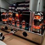
    I have just got a new to me Dynaco ST-70 Series 2, and are about to start work on it.

    I have already got replacement Elec Caps, so that will be the first job when time allows.

    The chassis is a little battered & bruised in places so I will probably remove the transformers to allow a little panel beating to be carried out safely.

    So now the request for help Very Happy 

    The original bias resistors fitted are 15ohm, not 15.6ohm as stated on the circuit.
    If I replace these with some 10ohm 2 watt (that I have in my bits box), would the bias circuit still work with the hi-lo leds and give a lower bias current ??

    I am also thinking of doing the Triode mod, and putting the switches on the front in place of the input rca's.
    And also removing the unused 16ohm speaker connectors, and putting new insulated input sockets on the rear. (I don't like uninsulated sockets grounded to the chassis on the front)

    What else should I replace or check?


    John


    Last edited by offanonone on Tue Jul 29, 2014 9:37 am; edited 1 time in total (Reason for editing : Corrected some of my bad spelling!!)
    avatar
    Guest
    Guest


    ST-70 Series 2 refurbishment Empty Re: ST-70 Series 2 refurbishment

    Post by Guest Tue Jul 29, 2014 8:26 am

    my best advise to you is to consider the VTA driver board upgrade, it will make a huge difference to the sound of the amp!
    It is available from Tubes4Hifi.com.
    Have you ran the amp at all?
    MarcVBelgium
    MarcVBelgium


    Posts : 116
    Join date : 2013-12-06
    Age : 71
    Location : Antwerp, BELGIUM

    ST-70 Series 2 refurbishment Empty ST 70 series 2

    Post by MarcVBelgium Tue Jul 29, 2014 9:26 am

    MontanaWay wrote:my best advise to you is to consider the VTA driver board upgrade, it will make a huge difference to the sound of the amp!
    It is available from Tubes4Hifi.com.
    Have you ran the amp at all?


    Forgive my interfering.... but as far as I know there is no VTA driver board for the series 2 ST70 (which was made by Panor in the nineties). On that amp, all the electronics is on one big PCboard, even the tubes...(I have one of those....)
    avatar
    offanonone


    Posts : 3
    Join date : 2014-07-17
    Location : Sheffield UK

    ST-70 Series 2 refurbishment Empty Re: ST-70 Series 2 refurbishment

    Post by offanonone Tue Jul 29, 2014 9:32 am

    MarcVBelgium wrote:
    Forgive my interfering.... but as far as I know there is no VTA driver board for the series 2 ST70 (which was made by Panor in the nineties). On that amp, all the electronics is on one big PCboard, even the tubes...(I have one of those....)

    Thanks for your reply Marc, and yes, its all on one board, so none of the aftermarket driver boards are a drop in replacement.

    As these are quite scarce in the UK, I want to keep it close to the original, with any mods easily reversable.

    John
    avatar
    Guest
    Guest


    ST-70 Series 2 refurbishment Empty Re: ST-70 Series 2 refurbishment

    Post by Guest Tue Jul 29, 2014 10:10 am

    ah ok, thanks for the correction, was not aware of that :-)
    peterh
    peterh


    Posts : 1869
    Join date : 2012-12-25
    Location : gothenburg, sweden

    ST-70 Series 2 refurbishment Empty Re: ST-70 Series 2 refurbishment

    Post by peterh Tue Jul 29, 2014 10:32 am

    offanonone wrote:Hello to everyone from a new member in the UK.

    I have just got a new to me Dynaco ST-70 Series 2, and are about to start work on it.

    I have already got replacement Elec Caps, so that will be the first job when time allows.

    The chassis is a little battered & bruised in places so I will probably remove the transformers to allow a little panel beating to be carried out safely.

    So now the request for help Very Happy 

    The original bias resistors fitted are 15ohm, not 15.6ohm as stated on the circuit.
    If I replace these with some 10ohm 2 watt (that I have in my bits box), would the bias circuit still work with the hi-lo leds and give a lower bias current ??

    I am also thinking of doing the Triode mod, and putting the switches on the front in place of the input rca's.
    And also removing the unused 16ohm speaker connectors, and putting new insulated input sockets on the rear. (I don't like uninsulated sockets grounded to the chassis on the front)

    What else should I replace or check?


    John
    The bias adjustment circuit depends on the "correct value" of cathode resistors. Why don't
    you let them be in place ?

    corndog71
    corndog71


    Posts : 840
    Join date : 2013-03-19
    Location : It can get windy here

    ST-70 Series 2 refurbishment Empty Re: ST-70 Series 2 refurbishment

    Post by corndog71 Tue Jul 29, 2014 11:17 am

    offanonone wrote:
    The original bias resistors fitted are 15ohm, not 15.6ohm as stated on the circuit.
    If I replace these with some 10ohm 2 watt (that I have in my bits box), would the bias circuit still work with the hi-lo leds and give a lower bias current ??

    John

    If I remember correctly the 15.6 Ohm resistors were an unusual value. If these were foreign made they probably went with whatever they had that was closest.
    http://www.dynakitparts.com/dynakit-products/bias-kit-parts/ST-70-BIAS-RESISTOR

    Personally, I prefer to use 10 Ohm resistors as they give you a more accurate reading but it won't match the label on the chassis.
    avatar
    offanonone


    Posts : 3
    Join date : 2014-07-17
    Location : Sheffield UK

    ST-70 Series 2 refurbishment Empty Re: ST-70 Series 2 refurbishment

    Post by offanonone Tue Jul 29, 2014 11:53 am

    The ST-70 Series 2, uses 2 led's that are adjusted with a multiturn pot until they are equal brightness. I assume with the original 15.6ohm resistors, that equal brightness would equate to 100mv or 50mv per tube.
    My question is would changing them to 10ohm still allow the bias adjustment to work in the same way, giving total 80mv and when the led's are equal, a balanced 40mv each tube ??


    John
    anbitet66
    anbitet66


    Posts : 143
    Join date : 2009-12-23
    Location : Valley Stream, NY

    ST-70 Series 2 refurbishment Empty Re: ST-70 Series 2 refurbishment

    Post by anbitet66 Tue Jul 29, 2014 12:22 pm

    John,

    If you look at your schematic, there are 2 resistors to set the brightness of an LED that you will use to compare while you adjust the bias with the other LED.  It is these resistors (R10= 6.65K and R4= 1k) which sets the LED brightness at 1.56 volts.  If you change R10 or R4, you can adjust the circuit to whatever conditions you'd like.  If you want to go to say a 10 ohm resistor for bias, and you are looking for 40mA per tube, then you will need an 0.8V drop on the 10 ohm resistor.

    The next problem will be getting the bias circuit to match.  By my calculations, if you change R4 to a 470 ohm resistor, you will set the voltage divider network to output a voltage of almost exactly 0.8 volts, matching the new bias you are looking for.

    Lets wait to see if anyone else agrees with me  scratch  .  I need to wait for the smoke to clear with all that thinking I had to do anyway...

    Tony
    Roy Mottram
    Roy Mottram
    Admin


    Posts : 1838
    Join date : 2008-11-30

    ST-70 Series 2 refurbishment Empty Re: ST-70 Series 2 refurbishment

    Post by Roy Mottram Sat Aug 02, 2014 7:21 pm

    Tony has it almost correct, I calculate a slightly different value. If you replace the 15 ohm R8 and R9 cathode resistors with 10 ohms,
    you will need to change R4 which sets up the window for the LEDs. The 1K R4 sends 1.56v to compare to cathode bias of 50ma per tube.
    Using 10 ohm resistors at R8 & R9 you would want R4 to be 510 ohm to correct the change, and 0.85v would indicate 40ma per tube.
    If you need the manual or schematic it is on my website here: www.tubes4hifi.com/downloads.htm
    The ST70 series 2 is about half way down the page, third row, 2nd from right.

    avatar
    Dogstar


    Posts : 361
    Join date : 2014-06-23

    ST-70 Series 2 refurbishment Empty Re: ST-70 Series 2 refurbishment

    Post by Dogstar Tue Aug 05, 2014 8:59 pm

    Can you post a photo of that amp?

    Sponsored content


    ST-70 Series 2 refurbishment Empty Re: ST-70 Series 2 refurbishment

    Post by Sponsored content


      Current date/time is Tue Nov 26, 2024 1:59 pm