
has anyone here used, or know of, an alternate to the electrolytic can capacitor used in the above amps, ie, using multiple single value capacitors, thanks.
+3
Bob Latino
mazeeff
corndog71
7 posters
alternate electrolytic capacitor for the ST-70/120 & M125

Guest- Guest
- Post n°1
 alternate electrolytic capacitor for the ST-70/120 & M125
![]() by Guest Mon Aug 25, 2014 1:39 am
by Guest Mon Aug 25, 2014 1:39 am
corndog71- Posts : 840
Join date : 2013-03-20
Location : It can get windy here
- Post n°2
Re: alternate electrolytic capacitor for the ST-70/120 & M125
![]() by corndog71 Mon Aug 25, 2014 2:36 am
by corndog71 Mon Aug 25, 2014 2:36 am
MontanaWay wrote:has anyone here used, or know of, an alternate to the electrolytic can capacitor used in the above amps, ie, using multiple single value capacitors, thanks.
Yep. Although you're gonna need a bigger box.
The main power supply caps are 45uf, 220uf, and 45uf. The lower caps are for the driver circuit. Also 45uf.

Guest- Guest
- Post n°3
Re: alternate electrolytic capacitor for the ST-70/120 & M125
![]() by Guest Mon Aug 25, 2014 2:46 am
by Guest Mon Aug 25, 2014 2:46 am
corndog71 wrote:MontanaWay wrote:has anyone here used, or know of, an alternate to the electrolytic can capacitor used in the above amps, ie, using multiple single value capacitors, thanks.
Yep. Although you're gonna need a bigger box.
The main power supply caps are 45uf, 220uf, and 45uf. The lower caps are for the driver circuit. Also 45uf.
where did you buy those from
mazeeff- Posts : 155
Join date : 2014-01-06
Age : 69
Location : Grand Rapids, Michigan, USA
- Post n°4
Re: alternate electrolytic capacitor for the ST-70/120 & M125
![]() by mazeeff Mon Aug 25, 2014 3:37 pm
by mazeeff Mon Aug 25, 2014 3:37 pm
I am using the SDS Labs Cap Board, and am quite happy with it.
http://www.triodeelectronics.com/st70capupgrade.html
Mike
http://www.triodeelectronics.com/st70capupgrade.html
Mike
Guest- Guest
- Post n°5
Re: alternate electrolytic capacitor for the ST-70/120 & M125
![]() by Guest Mon Aug 25, 2014 3:47 pm
by Guest Mon Aug 25, 2014 3:47 pm
mazeeff wrote:I am using the SDS Labs Cap Board, and am quite happy with it.
http://www.triodeelectronics.com/st70capupgrade.html
Mike
yeah had a look at that, how did you wire the bias portion on the new ST-70?, also, the voltage of 500V would not be suitable for the new ST-70/120.
mazeeff- Posts : 155
Join date : 2014-01-06
Age : 69
Location : Grand Rapids, Michigan, USA
- Post n°6
Re: alternate electrolytic capacitor for the ST-70/120 & M125
![]() by mazeeff Mon Aug 25, 2014 4:38 pm
by mazeeff Mon Aug 25, 2014 4:38 pm
I am using the SDS board on a stock ST-70, and the board was already installed, when I purchased it.
Guest- Guest
- Post n°7
Re: alternate electrolytic capacitor for the ST-70/120 & M125
![]() by Guest Mon Aug 25, 2014 4:46 pm
by Guest Mon Aug 25, 2014 4:46 pm
mazeeff wrote:I am using the SDS board on a stock ST-70, and the board was already installed, when I purchased it.
ok, thanks
Guest- Guest
- Post n°8
Re: alternate electrolytic capacitor for the ST-70/120 & M125
![]() by Guest Mon Aug 25, 2014 5:09 pm
by Guest Mon Aug 25, 2014 5:09 pm
.
Last edited by PeterCapo on Wed Dec 02, 2020 3:14 am; edited 2 times in total (Reason for editing : Correction.)
corndog71- Posts : 840
Join date : 2013-03-20
Location : It can get windy here
- Post n°9
Re: alternate electrolytic capacitor for the ST-70/120 & M125
![]() by corndog71 Mon Aug 25, 2014 6:32 pm
by corndog71 Mon Aug 25, 2014 6:32 pm
MontanaWay wrote:
where did you buy those from
They recently changed them to 600VDC versions with some having "Kelvin" connections vs. bolt style terminals. Mine are the older 700VDC versions.
http://www.partsconnexion.com/capacitor_film_clarity_tc6.html

Bob Latino- Admin
- Posts : 3263
Join date : 2008-11-27
Location : Massachusetts
- Post n°10
Re: alternate electrolytic capacitor for the ST-70/120 & M125
![]() by Bob Latino Mon Aug 25, 2014 7:11 pm
by Bob Latino Mon Aug 25, 2014 7:11 pm
Just to interject here .. Sometimes a tube amp can have TOO MUCH DC storage capacitance .. You can, if you keep adding capacitance, reach a point where the whole discharge/recharge cycle of the DC storage caps will slow down the rate of discharge/recharge of these caps. This CAN affect the sound of the amp especially at higher volume levels and higher frequencies. To avoid this situation you can add a "bypass capacitor". (as found on both the VTA ST-120 and the VTA M-125 monoblocks) The bypass capacitor allows a low impedance path to ground and will break up any resonances in the amp's high voltage storage caps.
Case in point .. The VTA ST-120 has 575 uF of DC storage for the driver board and output transformers ... I have added more capacitance to the VTA ST-120 and found that it doesn't really help the amp sound any better, have better bass, have better treble, play any louder or allow the amp to produce more power. Same thing for the M-125. As an aside, I had a fellow from Minnesota who "hopped up" the driver circuit of his M-125's to where he (according to him) got 200 watts out of each M-125 amp without altering the amp's power supply. He said that the only thing he noticed was that each of the amp's output transformers got noticeably warmer than normal.
Bob
dmtparker- Posts : 14
Join date : 2014-09-25
Location : Bocas del Toro, Panama
- Post n°11
Re: alternate electrolytic capacitor for the ST-70/120 & M125
![]() by dmtparker Fri Sep 26, 2014 12:17 am
by dmtparker Fri Sep 26, 2014 12:17 am
I tried the SDS boards and they worked quite well for about a year. Then they literally exploded. The caps blew up. This was several years ago and maybe the quality is better now, but I wanted to put out the warning. I have no idea why they exploded after working well for so long, but it was a pretty impressive event!MontanaWay wrote:mazeeff wrote:I am using the SDS board on a stock ST-70, and the board was already installed, when I purchased it.
ok, thanks

Roy Mottram- Admin
- Posts : 1837
Join date : 2008-11-30
- Post n°12
Re: alternate electrolytic capacitor for the ST-70/120 & M125
![]() by Roy Mottram Sat Sep 27, 2014 6:58 am
by Roy Mottram Sat Sep 27, 2014 6:58 am
Holger and everyone,
in my experience the quality of the SDS boards is poor, however, not to worry about the voltage rating,
as the caps are connected in series with sharing resistors, thus using something like 400vdc rated caps and I would use 330K or 390K 1w or 2w resistors directly across the caps for sharing and bleeding, so the voltage rating is theoretically 800v but to play it safe would call it a 600v rating, so no problems with any of our amps (ST70, ST120, M125), and then use something like a 1uF 600v across the pair.
IMHO using a new upgraded quad cap is less expensive and does the job well.
It's cheaper and less expensive to buy 4 or 6 capacitors and resistors and wire them to terminal strips than waste $40 on an SDS PCB plus the cost of the caps and resistors. You only need 2 sections, the before (I use dual 68uf in series for 34uF equiviilent) and after the choke (I use dual 330uF for 165uF equivalent), and the VTA driver board adds another 400uF for everything but the output tubes.
Njrob likes this post
richtp- Posts : 49
Join date : 2011-11-19
Location : Sterling MI
- Post n°13
Re: alternate electrolytic capacitor for the ST-70/120 & M125
![]() by richtp Sun Dec 07, 2014 4:31 pm
by richtp Sun Dec 07, 2014 4:31 pm
I was thinking about adding capacitance to my ST-70 with a VTA driver board.
I already have a few 330uf 250v caps. Would something like this work? I used your suggested values and kind of copied the triode cap board circuit.
[url=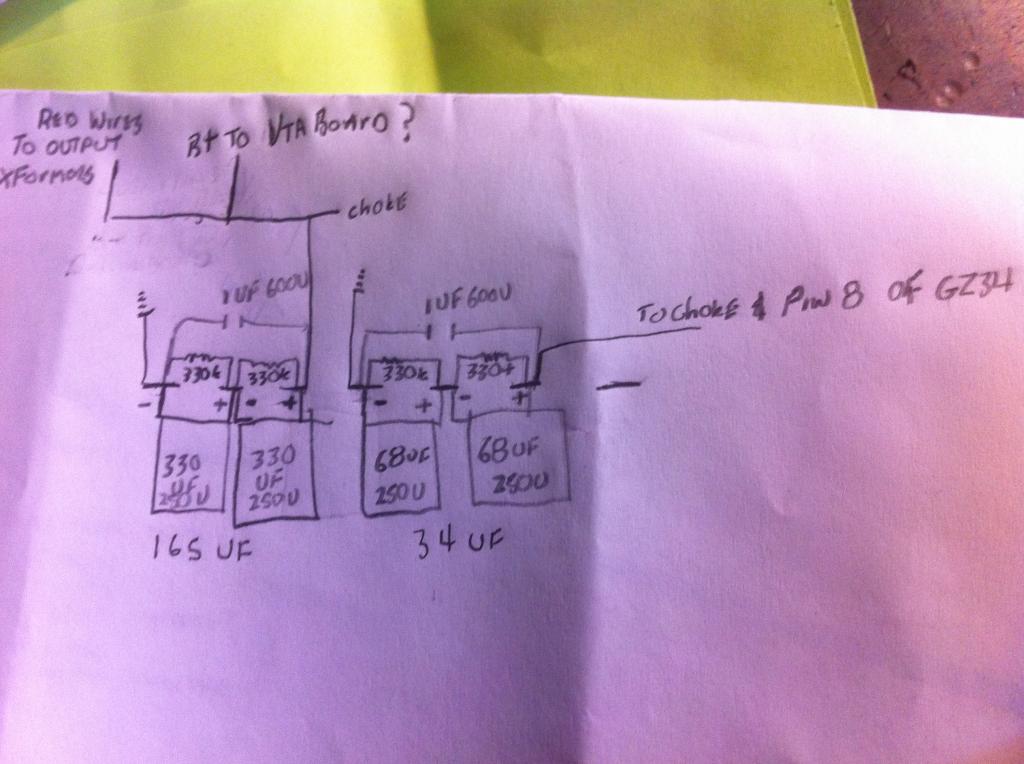 [/url]
I already have a few 330uf 250v caps. Would something like this work? I used your suggested values and kind of copied the triode cap board circuit.
[url=
[/url]
richtp- Posts : 49
Join date : 2011-11-19
Location : Sterling MI
- Post n°14
Re: alternate electrolytic capacitor for the ST-70/120 & M125
![]() by richtp Sun Dec 07, 2014 5:01 pm
by richtp Sun Dec 07, 2014 5:01 pm
Do I need to add the 22k resistor in there some place?

baddog1946- Posts : 319
Join date : 2010-02-03
Location : Costa Rica
- Post n°15
Re: alternate electrolytic capacitor for the ST-70/120 & M125
![]() by baddog1946 Sun Dec 07, 2014 5:41 pm
by baddog1946 Sun Dec 07, 2014 5:41 pm
Copied from this forum a year or two ago.
Baddog
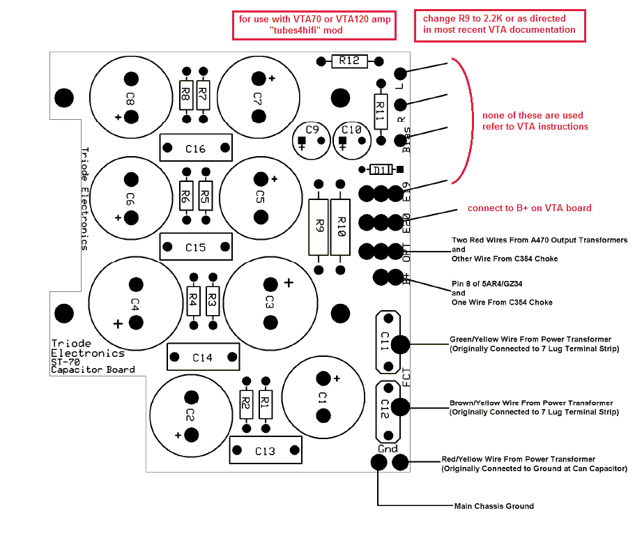
I know some people are interested in using combinations of the various after-market ST70 upgrades. Seeing as how both the SDS Capacitor/Power Supply board and VTA Driver are popular choices (and that installation directions for both assume they're being installed in an otherwise stock build), I thought I'd share how to utilize these boards in the same build.
The first thing to consider is whether or not you're going to use the the bias supply on the VTA board or the bias supply on the SDS Cap board. Since either way can make use of the bias potentiometer feature of the VTA board, there really is no better choice. However, if you plan on auditioning various drivers in your ST-70, it's probably best to use the SDS bias supply since not all driver PCBs include one.
If you choose to use the SDS Bias supply:
The following can be omitted from the VTA assembly: D1, C17 & C18, and R39. Otherwise, assemble it per the instructions.
No parts are omitted from the SDS assembly; once it is assembled, wire up the SDS per the instruction sheet, with the following exceptions:
Nothing is wired to eyelet "L"
Eyelet "R" on the SDS board is wired to the "B-" eyelet on the VTA board. If there is no "B-" eyelet on the VTA board, wire it to the right eyelet formerly reserved for R39 on the VTA PCB.
Eyelet "19" is wired to the eyelet marked "B+" on the VTA board.
Nothing is wired to Eyelet "20"
The VTA board can now be wired and installed as instructed, ignoring all references to the quad cap (replaced), red/black wire (already in use), and bias supply (redundant).
If you choose to use the VTA Bias supply:
The following can be omitted from the SDS assembly: D1, C9 & C10, and R11 & R12. Otherwise, assemble it per the instructions.
No parts are omitted from the VTA assembly. Go ahead and assemble it, but do not install or wire it.
Once the VTA board is assembled, set it aside and begin installing and wiring up the SDS board as instructed with the following exceptions:
Nothing is wired to eyelet "L"
Nothing is wired to eyelet "R"
Nothing is wired to eyelet "Bias"
Eyelet "19" is now wired to the eyelet marked "B+" on the VTA PCB
Nothing is wired to eyelet "20"
The VTA board can now be wired and installed as instructed, ignoring all references to the quad cap which has effectively been replaced.
Powering Up:
Follow the VTA board instructions in regard to initial power up and B+. If your B+ is too low (rising to 320VDC and settling well below the specified 400-440VDC), you may have to jumper either R9 or R10 (or both) on the SDS board make the B- settle between 400-440VDC.
The B- (bias supply) should measure around -50 to -55VDC where R39 meets the bias supply on the VTA board.
Additionally, you may want to retain the pair of 10K bias pots in the event you choose to revert the ST-70 to stock or come across a driver board that does not feature on-board biasing of the output tubes. Furthermore, the quad cap's sole purpose is now aesthetic, though one could install a Triode/Ultralinear switch instead.
Copied from this forum a year or two ago.
Baddog
To use the SDS cap board with the VTA driver board R9 on the SDS board should be (as Roy mentioned) a 2200 or 2.2K (2 or 3 watt) resistor. You then place a jumper in R10 if you have the VTA driver board.
If you have a STOCK ST-70 driver board, then R9 on the SDS cap board should be a 22,000 ohm (22K) resistor and R10 should be a 6800 (6.8K) resistor. Both of these resistors should be 2 or 3 watt.
Baddog
I know some people are interested in using combinations of the various after-market ST70 upgrades. Seeing as how both the SDS Capacitor/Power Supply board and VTA Driver are popular choices (and that installation directions for both assume they're being installed in an otherwise stock build), I thought I'd share how to utilize these boards in the same build.
The first thing to consider is whether or not you're going to use the the bias supply on the VTA board or the bias supply on the SDS Cap board. Since either way can make use of the bias potentiometer feature of the VTA board, there really is no better choice. However, if you plan on auditioning various drivers in your ST-70, it's probably best to use the SDS bias supply since not all driver PCBs include one.
If you choose to use the SDS Bias supply:
The following can be omitted from the VTA assembly: D1, C17 & C18, and R39. Otherwise, assemble it per the instructions.
No parts are omitted from the SDS assembly; once it is assembled, wire up the SDS per the instruction sheet, with the following exceptions:
Nothing is wired to eyelet "L"
Eyelet "R" on the SDS board is wired to the "B-" eyelet on the VTA board. If there is no "B-" eyelet on the VTA board, wire it to the right eyelet formerly reserved for R39 on the VTA PCB.
Eyelet "19" is wired to the eyelet marked "B+" on the VTA board.
Nothing is wired to Eyelet "20"
The VTA board can now be wired and installed as instructed, ignoring all references to the quad cap (replaced), red/black wire (already in use), and bias supply (redundant).
If you choose to use the VTA Bias supply:
The following can be omitted from the SDS assembly: D1, C9 & C10, and R11 & R12. Otherwise, assemble it per the instructions.
No parts are omitted from the VTA assembly. Go ahead and assemble it, but do not install or wire it.
Once the VTA board is assembled, set it aside and begin installing and wiring up the SDS board as instructed with the following exceptions:
Nothing is wired to eyelet "L"
Nothing is wired to eyelet "R"
Nothing is wired to eyelet "Bias"
Eyelet "19" is now wired to the eyelet marked "B+" on the VTA PCB
Nothing is wired to eyelet "20"
The VTA board can now be wired and installed as instructed, ignoring all references to the quad cap which has effectively been replaced.
Powering Up:
Follow the VTA board instructions in regard to initial power up and B+. If your B+ is too low (rising to 320VDC and settling well below the specified 400-440VDC), you may have to jumper either R9 or R10 (or both) on the SDS board make the B- settle between 400-440VDC.
The B- (bias supply) should measure around -50 to -55VDC where R39 meets the bias supply on the VTA board.
Additionally, you may want to retain the pair of 10K bias pots in the event you choose to revert the ST-70 to stock or come across a driver board that does not feature on-board biasing of the output tubes. Furthermore, the quad cap's sole purpose is now aesthetic, though one could install a Triode/Ultralinear switch instead.
Copied from this forum a year or two ago.
Baddog
To use the SDS cap board with the VTA driver board R9 on the SDS board should be (as Roy mentioned) a 2200 or 2.2K (2 or 3 watt) resistor. You then place a jumper in R10 if you have the VTA driver board.
If you have a STOCK ST-70 driver board, then R9 on the SDS cap board should be a 22,000 ohm (22K) resistor and R10 should be a 6800 (6.8K) resistor. Both of these resistors should be 2 or 3 watt.

richtp- Posts : 49
Join date : 2011-11-19
Location : Sterling MI
- Post n°16
Re: alternate electrolytic capacitor for the ST-70/120 & M125
![]() by richtp Sun Dec 07, 2014 6:30 pm
by richtp Sun Dec 07, 2014 6:30 pm
Thank you!I have been reading through a lot of posts on here but didn't see this one.
From what I see here and looking at the SDS (triode) cap board. I would add the 22k resistor between the + of the 165uf section and the + of the 34uf section in my drawing. Right?
From what I see here and looking at the SDS (triode) cap board. I would add the 22k resistor between the + of the 165uf section and the + of the 34uf section in my drawing. Right?
Roy Mottram- Admin
- Posts : 1837
Join date : 2008-11-30
- Post n°17
Re: alternate electrolytic capacitor for the ST-70/120 & M125
![]() by Roy Mottram Sun Dec 07, 2014 9:28 pm
by Roy Mottram Sun Dec 07, 2014 9:28 pm
The 22K resistor is only needed if you are using a stock original Dynaco PC3 driver board, it is never used with the VTA mod
richtp- Posts : 49
Join date : 2011-11-19
Location : Sterling MI
- Post n°18
Re: alternate electrolytic capacitor for the ST-70/120 & M125
![]() by richtp Sun Dec 07, 2014 10:13 pm
by richtp Sun Dec 07, 2014 10:13 pm
Whoops! I meant 2.2k I was looking at the original schematic.
Sponsored content