VTA ST-70 with EL34 or 6L6 output tubes > recommended bias setting is .40 VDC per each output tube which gives a bias current of 40 milliamps per each output tube.
VTA ST-70 with KT66 or KT77 output tubes > recommended bias setting is .45 VDC per each output tube which gives a bias current of 45 milliamps per each output tube.
VTA ST-70 with 6550 or KT88 output tubes > recommended bias setting is .50 VDC per each output tube which gives a bias current of 50 milliamps per each output tube.
------------------------------------------------------------------------------------------------------------------------------------------------------------------------
VTA ST-120 with 6550, KT88 or KT120 output tubes > recommended bias setting is .50 VDC per each output tube which gives a bias current of 50 milliamps per each output tube.
------------------------------------------------------------------------------------------------------------------------------------------------------------------------
VTA M-125 with 6550, KT88 or KT120 output tubes USING TWO OUTPUT TUBES PER AMP > recommended setting is .50 VDC per each side which gives a bias current of 50 milliamps per each output tube.
VTA M-125 with 6550, KT88 or KT120 output tubes USING FOUR OUTPUT TUBES PER AMP > recommended setting is 1.00 VDC per each side which gives a bias current of 50 milliamps per each output tube.
All the user manuals will be changed to reflect the new bias recommendations ...
Bob
VTA ST-70 KIT assembly video below. This KIT video was done by VTA ST-70 amp builder Rick Green from FL. The video does not show all the wiring steps but does give a good idea of how the VTA ST-70 amp is assembled. Note that this amp has the older two post binding posts. All the new VTA amps (kit or wired) have THREE post binding posts and may be set up for any TWO impedances (4 and 8 ohm, 4 and 16 ohm, 8 and 16 ohm).
Review Home Theater and Hi-Fi > The VTA ST-120
Review Home Theater and Hi-Fi > The VTA M-125
Another VTA M-125 review > VTA M-125 review from 2015
VTA Tube Amp Kits Facebook page > Facebook > VTA Tube Amp Kits
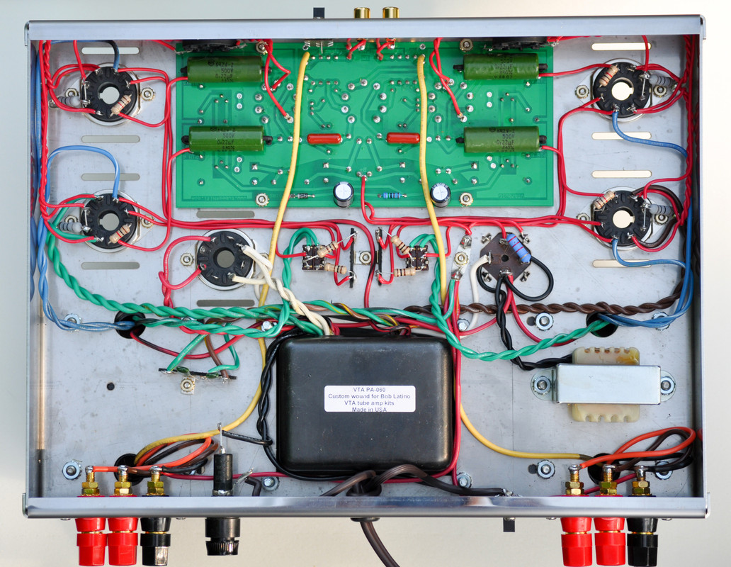
VTA ST-70 amp wiring photo below

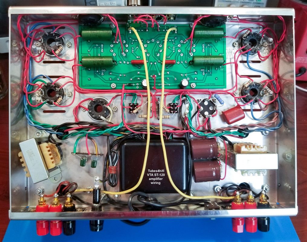
VTA ST-120 amp wiring photo below

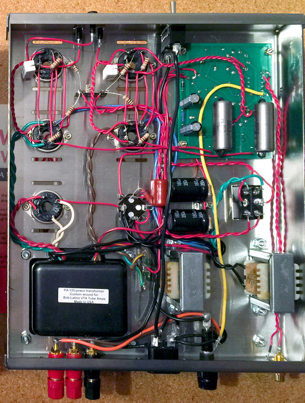
VTA M-125 amp wiring below

ADDED on 3/5/20 > In certain parts of the USA and Canada line voltages can be higher than normal. While 120 VAC is supposed to be the norm, customers have reported to me voltages in the 122 to 125 VAC range. These higher than normal line voltages can cause shorter than normal tube life in your tube amp > especially the rectifier. In order to counteract this issue, all the VTA ST-120 and VTA M-125 monoblock amps will now come with DUAL PRIMARY connections. If your line voltage is normal (below 121 VAC), you use the standard connection. If your line voltage is 121 VAC or higher, you use the alternate connection which will drop the voltages on the secondary windings by about 2 1/2 %. Example > If your line voltage is 124 VAC, using the alternate connection will cause everything on the secondary side of the transformer to give out AC voltages as if your line voltage was about 120.28 VAC.
Added on 5/19/20 > How to bias your VTA ST-70 or VTA ST-120 amp - see below (ST-70 bias is .400 VDC per each output tube and ST-120 bias is .500 VDC)
For the VTA ST-120 for the year 2012 to present day ...
1. Set you multimeter to the 0 to 2 volt DC scale
2. Place the black probe on the chassis and the red probe in the front LEFT tube socket pin that says "Biaset 1.56 V". Adjust the bias pot on the driver board next to the front left tube so that the meter reads .500 volts DC (that is POINT 5 volts DC or 1/2 volt DC). Next place the red probe in the front tube socket pin that is OPPOSITE the pin that you just used. Use the rear bias pot on the left channel to adjust the rear left output tube to .500 volts DC. If you have a VTA ST-70, then the bias will be .400 volts DC instead of .500 volts DC.
3. Do the same as #2 above for the right channel
Facts about bias below ..
Since all tubes share the bias current > as you adjust one tube UP, the other tubes will go DOWN very slightly. Go back and forth between the four output tubes until all are between .490 and .510. That is plenty close enough. You will never all four output tubes to stay at .500 exactly.
As the amp warms up from a cold start, the bias will rise very slightly over the first half hour. After 1/2 hour recheck the bias and reset the output tubes so that all are between .490 and .510 VDC.
If all your tubes have a wandering bias UP or DOWN over time, then probably your line voltage is wandering UP and DOWN.
If just ONE tube just cannot be biased at .500, then that tube is probably bad or going bad OR possibly the 10 ohm 2 watt resistor that goes from pins 1/8 to chassis ground is bad and does not measure 10 ohms anymore.
If ALL tubes cannot be biased, then probably your rectifier has a problem.
Check your bias about once a month. As the output tubes wear in, the bias will change slightly. Check out the "setting the bias on a VTA ST-120" video at the link below. Setting the bias on a VTA ST-70 is the exactly the same except the bias is set lower (.400 VDC per each output tube) on the VTA ST-70.
Link - Setting the bias on a VTA ST-120
Added on 6/14/20
Facts about VTA amp capacitor upgrades
1. Power capacitor upgrade - On the VTA ST-70/ST-120 are four electrolytic capacitors that supply power to run the board. The upgraded caps are four low ESR (equivalent series resistance) 100 uF @ 400 volt Nichicon caps which are made in Japan. These four caps are physically larger and discharge and recharge at a very slightly faster than the stock power caps. When the amp is played loud these upgraded caps tend to "keep up with the music" a little better. The two bias supply caps are also Nichicon caps. On the VTA ST-120 the SCM (supplementary cap module) are two quality Elna caps which are also made in Japan. The Nichicon and Elna caps are much better than your average Chinese electrolytic caps. Note > There are no Chinese electrolytic caps anywhere on any VTA amp.
2. Russian PIO main coupling capacitor upgrade - These four capacitors are directly in the signal path. Their job is to take the audio signal from the driver board circuit and pass the audio to each one of the four output tubes. Because they are directly in the signal path, they do have a noticeable influence on the sound of the amp. The most common Russian PIO series used today in audio amps are the K42Y-2, the K75-10 and the K75-24. All three sound very similar .. These caps seem to give a better sense of "space" than standard film capacitors. They give a very large soundstage. On well engineered recordings you can really get an accurate sense of where each instrument is in the soundstage.
Note > Power supply and Russian PIO caps are optional on the VTA ST-70 and VTA ST-120 but are standard equipment on our VTA M-125 monoblock amps.
Added on 6/16/20 > Autobias boards ..
I cannot recommend anymore the autobias boards sold by 3rd party vendors for the VTA ST-70, VTA ST-120 and VTA M-125 amps. These boards are made by Audioamp.eu in the Czech Republic and are now distributed by a USA seller in Arizona. These boards do work properly when installed but the problem has been long term durability of the board itself. I have had now
Bob
Last edited by Bob Latino on Mon Aug 22, 2022 7:59 am; edited 22 times in total


