The Dynaco Tube Audio Forum

Would you like to react to this message? Create an account in a few clicks or log in to continue.
The Dynaco Tube Audio Forum

Dedicated to the restoration and preservation of all original Dynaco tube audio equipment - Customer support for Tubes4hifi VTA tube amp and preamp kits and all Dynakitparts.com products


+6
aguaazul
pedrocols
ericoto
Roy Mottram
deepee99
Skydogcable
10 posters

    Issues with M125 after Auto Bias install

    avatar
    Skydogcable


    Posts : 28
    Join date : 2018-12-04

    Issues with M125 after Auto Bias install Empty Issues with M125 after Auto Bias install

    Post by Skydogcable Tue Dec 11, 2018 2:58 pm

    Has anyone out there successfully installed an Auto Bias board on an M125? After the install the amp is significantly less loud and the audio sounds clipped.
    The clipped audio may be due to the fact that I'm having to crank up the preamp.  Any insight would be greatly appreciated.


    Issues with M125 after Auto Bias install AB-M125install19
    avatar
    Guest
    Guest


    Issues with M125 after Auto Bias install Empty Re: Issues with M125 after Auto Bias install

    Post by Guest Wed Dec 12, 2018 10:50 am

    I assume you pre adjusted the trimmer on the AB pcb as per the instructions? I would set it at 500 to 525mV if you're using KT120's. Of course, once set, BEFORE the AB gets connected to the amp, it should not need adjusting again.
    Does it behave the same in Triode or Pentode mode?
    avatar
    Skydogcable


    Posts : 28
    Join date : 2018-12-04

    Issues with M125 after Auto Bias install Empty Re: Issues with M125 after Auto Bias install

    Post by Skydogcable Wed Dec 12, 2018 12:30 pm

    I did that for the first one but per Roy the boards are preset for 50 mA at the reference point. Perhaps I should pull this one out and re-calibrate. The instructions said I should measure 50 mA at the reference point. Should I measure mA or mV? I'm currently running Sovtek 6550's but as soon as I think the amp is solid I plan on rolling over to some Gold Lion KT88's. I'm currently experiencing the issue in pentode mode. I will test the amp later today in triode mode and report back. Thanks!

    Brandon3212276 likes this post

    avatar
    Skydogcable


    Posts : 28
    Join date : 2018-12-04

    Issues with M125 after Auto Bias install Empty Re: Issues with M125 after Auto Bias install

    Post by Skydogcable Wed Dec 12, 2018 12:31 pm

    From the manual:

    Initial Setup
    The module is not connected in the amplifier. Apply the AC voltage taken from the filament supply
    of the tubes (6.3...vac). Wait for the green LED (indicating the ramp up of the reference voltage) to
    light up. P2 trimmer is used to set the reference voltage which determines the quiescent current through
    the tubes. S2 jumper is connected.
    Use the following formula: Vref = 0.5V, then Io = 0.5/10 = 0.05 = 50mA per tube. Vref is measured
    between the “Ref” point and the ground.
    The S2 jumper on the module connects the driver board bias for generating the reference voltage.
    deepee99
    deepee99


    Posts : 2244
    Join date : 2012-05-23
    Location : Wallace, Idaho

    Issues with M125 after Auto Bias install Empty Re: Issues with M125 after Auto Bias install

    Post by deepee99 Wed Dec 12, 2018 12:44 pm


    Yes. It sets the actual bias that will appear on the output tubes. The trimmer is every bit as sensitive to adjustments as the original plastic trim pots supplied with the VTA series and bias needs to be checked with the amp upside down, running with output tubes, warmed-up (20 minutes or so) and of course a dummy load or speaker. That reading may be double-tested by measuring volts across the green cathode resistors; all should agree. It should stay put after that. If it doesn't, the trim pot itself is one likely source of the problem. At least it was in my case. Turned out (I theorize here) there was a microscopic and heat-sensitive piece of crud destabilizing the bias trimmer's behaviour as measured at the test points (Sachs KT88 amp, based in part on the VTA ST-120 save for the transformers and solid-state power supply). I made note of where the trim screw was set originally, then ran the screw itself up and down stop-to-stop a couple of times, then back to its original set-point, and it has been rock-steady stable after that. If all behaves well, and then the bias reading on one tube is out of whack with the others, it's likely the tube is telling you it's bed-time.
    avatar
    Guest
    Guest


    Issues with M125 after Auto Bias install Empty Re: Issues with M125 after Auto Bias install

    Post by Guest Wed Dec 12, 2018 1:02 pm

    I use mV, an old habit from manual bias adjustment. For KT120's I set 0.525mV, for KT88's I set 0.450mV so for 6550's I would set 0.450mV or even 0.425mV. I have always been a bit conservative with bias, as I never did see any advantage in pushing the output tubes!
    I power up the AB pcb with 9VAC, that's what I happen to have, which is not yet connected to the amp, wait until the RED led D30 goes out, then put the black meter lead on a GND pad and the red on the small pad next to C13, then adjust the trimmer as per above.
    Meter is set to DC volts, in my case it is auto adjust, or set to say 2V scale or similar.
    avatar
    ericoto


    Posts : 26
    Join date : 2013-12-11

    Issues with M125 after Auto Bias install Empty Same Problem

    Post by ericoto Mon Dec 17, 2018 7:41 am

    I also note the same problem. Initially after I installed, seemed to saturate easily with an audible cracking, particularly at loud passage. Seemed to resolve, I hadn't used the M125 for awhile after working on another project. After setting back up, clipping/cracking still present. Results n harsh tone. Though it might be speakers, but still present with a different set. Biases OK at .50V using Kt120 tubes that sounded fine prior, sound is also in both channels, Any thoughts? Has anyone else heard it? Any thoughts on a fix?
    avatar
    Skydogcable


    Posts : 28
    Join date : 2018-12-04

    Issues with M125 after Auto Bias install Empty Re: Issues with M125 after Auto Bias install

    Post by Skydogcable Mon Dec 17, 2018 9:34 am

    I’m sorry that you are having issues but glad to hear that I’m not the only one. Mine did the same thing. It biased fine on all 4 tubes and everything seemed fine. However it was clipped and the voltage measured on the speaker out at just below clip was .8 V. They also both had an exagerated noise floor. I ended up pulling mine out and both amps returned to being dead quiet and full power.
    avatar
    Skydogcable


    Posts : 28
    Join date : 2018-12-04

    Issues with M125 after Auto Bias install Empty Re: Issues with M125 after Auto Bias install

    Post by Skydogcable Mon Dec 17, 2018 9:39 am

    Probably worth noting that I had the same issues with a tube and SS rectifier as well as 2 different sets of known good output and driver tubes. Also my line voltage is rock solid 120v. I wonder if it was a bad run of cards or if the m125 AB cardbhas a design issue. Has anyone got one to successfully work?
    avatar
    Guest
    Guest


    Issues with M125 after Auto Bias install Empty Re: Issues with M125 after Auto Bias install

    Post by Guest Mon Dec 17, 2018 12:28 pm

    I am using the AB-Q module in all my power amp builds and they have been performing excellently.
    Circuit wise, I understand that they are identical to the M125 AB module, the only difference is that for the M125, one has to add the additional two coupling caps and resistor and that is only due to the layout of the M125 VTA pcb and hence the different shape of the AB module pcb for the M125.
    I very much doubt there is a design issue with Pavel's AB modules. And with all the AB-Q modules I have so far used, not one has been faulty.
    avatar
    ericoto


    Posts : 26
    Join date : 2013-12-11

    Issues with M125 after Auto Bias install Empty Re: Issues with M125 after Auto Bias install

    Post by ericoto Mon Dec 17, 2018 1:17 pm

    Well, the M125 I have worked great prior to the AB board was added, and other than putting in the board nothing was changed, it is also in both channels. Has anyone experience with installing on an M125 w/o having issues?
    deepee99
    deepee99


    Posts : 2244
    Join date : 2012-05-23
    Location : Wallace, Idaho

    Issues with M125 after Auto Bias install Empty Re: Issues with M125 after Auto Bias install

    Post by deepee99 Mon Dec 17, 2018 1:49 pm

    Please excuse the obvious, but I'd sure suspect the solder connections to the AB board. They are tight and one could easily look soldered when it ain't. Give 'em all a good yank.
    Pavel's board at least allows you to check bias on each tube. There is a "master adjustment" if you will on the board but adjustment requires flipping the amp(s) over and tweaking the trim pot, which is that tall blue thing with a brass screw (the actual adjuster). Very slight movements of that screw will produce big changes in the master bias, so best to check it with tubes on, on a dummy load or speaker attached to the speaker ledes. (Expect a loud hum if the signal inputs aren't muted by (f'r instance) a pre-amp connected to an unused input. That's best, anyway; if you've got music running the bias reading will constantly be changing.)
    If I had one change to make in Pavel's board, it would be to have that master bias trimmer-pot exposed from the top or front of the amplifier, the way they are on Bob L.'s builds, so it doesn't take an act of Congress to get to it.
    avatar
    Guest
    Guest


    Issues with M125 after Auto Bias install Empty Re: Issues with M125 after Auto Bias install

    Post by Guest Mon Dec 17, 2018 2:04 pm

    deepee99 wrote:Please excuse the obvious, but I'd sure suspect the solder connections to the AB board. They are tight and one could easily look soldered when it ain't. Give 'em all a good yank.
    Quoth Peter W. "But, the point is that self-adjusting bias is good, when it works. Manually-adjusted bias keeps one 'in touch' with one's equipment, and provides a heightened awareness of its condition. Not necessarily a bad thing."

    Peter, Pavel's board at least allows you to check bias on each tube. There is a "master adjustment" if you will on the board but adjustment requires flipping the amp(s) over and tweaking the trim pot, which is that tall blue thing with a brass screw (the actual adjuster). Very slight movements of that screw will produce big changes in the master bias, so best to check it with tubes on, on a dummy load or speaker attached to the speaker ledes. (Expect a loud hum if the signal inputs aren't muted by (f'r instance) a pre-amp connected to an unused input. That's best, anyway; if you've got music running the bias reading will constantly be changing.)
    If I had one change to make in Pavel's board, it would be to have that master bias trimmer-pot exposed from the top or front of the amplifier, the way they are on Bob L.'s builds, so it doesn't take an act of Congress to get to it.

    the idea of having the bias trimmer away from easy access is that once bias is adjusted, for a certain model/family of tubes, it should never be adjusted again! That is the whole idea of auto bias. If that trimmer is placed where it is easy to access, it just calls for trouble! Perhaps not so much for us who know what they are doing, but for those who do not and would just adjust away without understanding the consequences!
    Of course, if one were to change the model of output tubes, then even the AB module would need to be readjusted to the correct bias value for those different model tubes. And then this starts a whole new discussion/argument about the pro and cons of tube rolling and trying different output tubes that would need a different bias value.....don't get me started on this one!! Evil or Very Mad

    And yes, going with my experience using the AB-Q, I would say it is not an issue with the AB-Q, but something was perhaps not done correctly with the installation/wiring. Double, then triple check everything again.

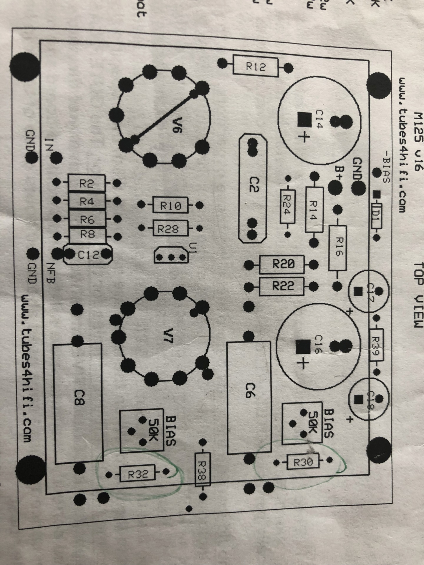
    As to the labeling of the pcb, well, for the M125, it is a custom design to suit ONLY the M125, that would be the reason for the different model/type name. However, the actual circuit, as far as I know, is identical to the AB-Q.
    avatar
    Skydogcable


    Posts : 28
    Join date : 2018-12-04

    Issues with M125 after Auto Bias install Empty Re: Issues with M125 after Auto Bias install

    Post by Skydogcable Mon Dec 17, 2018 2:57 pm

    It’s my luck that if there is a 1 in a million chance for a lemon, I’ll be the one to get that lemon. That being said I’m still hoping for someone to point out a stupid mistake made by me. By giving up and shipping the boards back I’m giving up on the puzzle which i have to admit hurts my tech guy ego a bit. Smile
    avatar
    Guest
    Guest


    Issues with M125 after Auto Bias install Empty Re: Issues with M125 after Auto Bias install

    Post by Guest Mon Dec 17, 2018 2:57 pm

    looking at your photos, did you add the two isolation resistors, known as R30 & R32 on the overall M125 AB pcb wiring diagram, see attached, they are located at the bottom of the diagram, around the 100K value?
    Two isolation resistors are already on the M125 AB pcb, but you will still need to add another pair as well.

    Issues with M125 after Auto Bias install NfgIcd
    avatar
    Skydogcable


    Posts : 28
    Join date : 2018-12-04

    Issues with M125 after Auto Bias install Empty Re: Issues with M125 after Auto Bias install

    Post by Skydogcable Mon Dec 17, 2018 3:02 pm

    These?

    Issues with M125 after Auto Bias install 5471fd10
    avatar
    Skydogcable


    Posts : 28
    Join date : 2018-12-04

    Issues with M125 after Auto Bias install Empty Re: Issues with M125 after Auto Bias install

    Post by Skydogcable Mon Dec 17, 2018 3:16 pm

    I think that we might be in to something. R30 and R32 are connected to the V1 and V2 GRD connection point. However I did not have them connected.
    avatar
    Guest
    Guest


    Issues with M125 after Auto Bias install Empty Re: Issues with M125 after Auto Bias install

    Post by Guest Mon Dec 17, 2018 3:34 pm

    Skydogcable wrote:I think that we might be in to something. R30 and R32 are connected to the V1 and V2 GRD connection point. However, I did not have them connected.

    and there should also be a pair, one each, connected to V3 & V4. With other words, each output tube needs to have one isolation resistor connected, in your case, 100K by the looks of it.
    Each resistor needs to be connected between the GRD pad on the AB pcb and at the junction of each coupling capacitor and grid stop resistors, refer to the diagram i attached in my last message. This 'connection' should already be done for V1 and V2 on the AB pcb.
    avatar
    Guest
    Guest


    Issues with M125 after Auto Bias install Empty Re: Issues with M125 after Auto Bias install

    Post by Guest Mon Dec 17, 2018 3:46 pm

    follow the wiring diagram I attached a couple of messages ago and make sure you add those two additional 100K 1W isolation resistors to V3 & V4. Connect them exactly as shown in that diagram and you should be good to go!
    Its the purple/violet wires and that 100K 1W resistor for each V3 & V4 tube!
    avatar
    Skydogcable


    Posts : 28
    Join date : 2018-12-04

    Issues with M125 after Auto Bias install Empty Re: Issues with M125 after Auto Bias install

    Post by Skydogcable Mon Dec 17, 2018 4:02 pm

    I think that the resistors for V3 and v4 tubes are on the main driver board. See the pic. Issues with M125 after Auto Bias install 8ec74210
    avatar
    Guest
    Guest


    Issues with M125 after Auto Bias install Empty Re: Issues with M125 after Auto Bias install

    Post by Guest Mon Dec 17, 2018 4:06 pm

    if they are retained on the VTA M125 pcb, then yes, they should be OK, but where to connect those two purple/violet wires, shown on the diagram, to the modified VTA M125 pcb I am not sure. I am assuming part of the mod is to remove the original 50K BIAS  trimmers.
    Check again to see if the instructions you got from Roy mention those two wires, I would assume they are.
    avatar
    Guest
    Guest


    Issues with M125 after Auto Bias install Empty Re: Issues with M125 after Auto Bias install

    Post by Guest Mon Dec 17, 2018 9:53 pm

    OK, so the purple/violet wire should go to the point/solder pad what was the trimmers wiper, thats how I see it. So you'll need to of course connect one purple/violet wire to what was the wiper of trimmer VR4 and one to what was the wiper of trimmer VR2. Make sure you use the correct connections for V3 & V4, don't mix them up, so, on the AB pcb, GRD for V3 should be connected to what was the wiper for the trimmer that now is the output circuit for tube V3 and GRD for V4 on the AB pcb should be connected to what was the wiper for the trimmer that is now the output circuit for tube V4.
    Perhaps Pavel can confirm this but I am also assuming this is included with the instructions from Roy?
    avatar
    Skydogcable


    Posts : 28
    Join date : 2018-12-04

    Issues with M125 after Auto Bias install Empty Re: Issues with M125 after Auto Bias install

    Post by Skydogcable Mon Dec 17, 2018 10:48 pm

    That makes sense to me. I actually still have the boards so I may hold them until I get some clarification from those guys. Thanks for your help working through this.
    avatar
    Guest
    Guest


    Issues with M125 after Auto Bias install Empty Re: Issues with M125 after Auto Bias install

    Post by Guest Mon Dec 17, 2018 10:50 pm

    Skydogcable wrote:That makes sense to me. I actually still have the boards so I may hold them until I get some clarification from those guys. Thanks for your help working through this.

    Yes, I am pretty sure connecting those two wires to the 'open' end of those 100K 1W resistors is the right way, but let's wait to hear from Roy and Pavel.
    Roy Mottram
    Roy Mottram
    Admin


    Posts : 1839
    Join date : 2008-11-30

    Issues with M125 after Auto Bias install Empty Re: Issues with M125 after Auto Bias install

    Post by Roy Mottram Tue Dec 18, 2018 11:40 am

    thanks Holger for trying to help, but nobody can get the full picture without looking AT the PICTURE !
    This was first posted last March in the original auto-bias thread, I have just updated the picture with a few yellow traces to show the connections on the auto-bias board so that you can see ALL of the
    connections the way they exist when it is wired according to the instructions supplied with the board.
    Follow the blue wires from the original M125 driver board on the left, to the AB board on the right.   You can see that we take the signals from just before C6 and C8,
    and they follow a parallel path thru another C6b and C8b, then connect to the needed 100K resistors, which also are connected via circuit board traces (the yellow ones)
    to V1-GRD for R30-C6b and to V2-GRD for R32-C8b.   If you took those blue wires from the wrong place on the original driver board then the AB board will not work correctly.
    The purple wires show the bias control voltage from the AB board going thru 100K then connecting to the 1K grid resistor, same path on all four tubes.
    Hope this clears things up for everyone.

    Issues with M125 after Auto Bias install Mk125-ABsch

    Sponsored content


    Issues with M125 after Auto Bias install Empty Re: Issues with M125 after Auto Bias install

    Post by Sponsored content


      Current date/time is Thu May 02, 2024 10:52 am