+4
Dynaco_wjw
mantha3
TN Allen
OldFrisco
8 posters
Rebuilding Mark IIIs
OldFrisco- Posts : 38
Join date : 2020-02-16
Location : San Francisco
- Post n°1
Rebuilding Mark IIIs
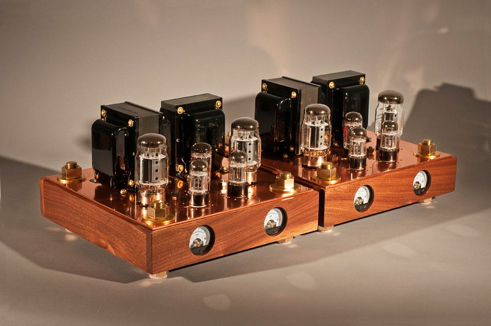
I'm rebuilding a pair of Mark IIIs with chassis I fabricated. I made new chassis for a few reasons. One, I wanted to make a mirror image pair. Also, I wanted to put Vu meters in the face plates. And I wanted to get rid of the Dynaco pcb hole. I mounted my Tubes4hifi driver boards underneath and inverted. I'm going to hard wire a pair of panel mount tube sockets and hide the pcbs. In doing this, I've opened up some space in the top panel and now need to locate and punch some holes for sockets. The dimensions are the same as stock chassis, with the transformers in the same positions. But purely for aesthetic reasons, I'm rotating the front of the amp 90º and moving the connectors and power socket to what is now the rear of the units. Originally, I'd planned on using Triode parts, but I paid for driver boards and four months later, I still didn't have them. So I asked around and found out about Tubes4hifi (wish I knew before hand). I already had the Triode power supply boards, so I only purchased the driver boards from Tubes4. Anyway, it's time to make final decisions for the top plates of the chassis. What I've planned so far is to move the KT88s a little forward on the plate and a little further apart, to give them more cooling room and put them in a horizontal line facing the front of the amps. I sent an email to Tubes4 asking if there is any way I can use the panel bias pots I bought from Triode. If I can use them, I need to drill holes for the shafts in the top plates, but there's plenty of room for that. So I'm attaching a couple photographs of what I'm doing, just to see if anyone says, "No! You've made a mistake." A lot of the changes I've made are purely for aesthetic reasons, so I don't care about getting them to look like stock Mark IIIs. But I need to locate the rectifier tube and was thinking of putting it a little over from and behind the outputs, almost on the middle line of the two transformers. Any thoughts about where rectifiers should and absolutely should not go?
TN Allen- Posts : 167
Join date : 2013-01-01
- Post n°2
Re: Rebuilding Mark IIIs
I like some of the changes to the original Dynaco layout you are trying. I tried a different layout and received many very useful suggestions from forum members (link below). I suspect others will have much better informed suggestions than what I might write.
One thing I have learned though, and perhaps you have already considered this, is to leave plenty of space around the various components to make assembling, soldering and later modifications easier. I'll be interested in reading the discussion regarding your proposed layout. https://dynacotubeaudio.forumotion.com/t2547-proposed-mark-iii-layout
mantha3- Posts : 303
Join date : 2010-11-10
- Post n°3
Re: Rebuilding Mark IIIs
Nice, where did you get the VU meters? Nice!
Dynaco_wjw- Posts : 14
Join date : 2013-11-28
- Post n°4
Re: Rebuilding Mark IIIs
Hello Oldfrisco,
Too bad you demolished a Dynaco Mark III. You had something beautiful and now you have nothing special. Why didn't you build a new amplifier with toroidal transformers and a good design. Then you could have kept the Dynaco, that is really a gem. Save all your Dynaco Mark III parts so that you can always go back to the Mark III. Nevertheless, success with your project.
Wim
Roy Mottram- Admin
- Posts : 1839
Join date : 2008-11-30
- Post n°5
Re: Rebuilding Mark IIIs
Scott,
I hope you are not doing what you literally say you are doing. You do not want to "invert" the driver boards, and then run wires to chassis sockets.
The simple solution is to invert the parts on the driver board, but NOT the sockets, and mount it where you want those tubes to stick out the top.
If you invert the sockets the tubes themselves will not be connected properly,
and if you run wires to separate sockets you'll be messing up the signals and getting all kinds of noise and possible oscillations.
If you haven't finished your layout yet, you might want to consider this one that I've done before . . .
Wharfcreek- Posts : 45
Join date : 2017-07-15
- Post n°6
Re: Rebuilding Mark IIIs
Old Frisco,
I'll be honest, I'm a bit confused by your plan....... or at least what I can figure out from what I see. Judging from the location of the tubes on the PC board, they wouldn't line up with where you have the hole locations indicated in the circles on the top panel. If you plan to line up both transformers along the back side (which I like), and then do the two output tubes front 'right' side, and two driver tubes front 'left' side....then my only consideration is that if you put the rectifier between them in any way, it would somewhat interfere with the signal path between the driver side and the opt's. Seems to me it would simply make more sense to locate the two output tubes more or less 'centered' in the front, the two driver tubes to one side, the the rectifier to the other side (same side as the PT). I take it the choke will be located under the top plate and 'within' the chassis as well? WC
OldFrisco- Posts : 38
Join date : 2020-02-16
Location : San Francisco
- Post n°7
Re: Rebuilding Mark IIIs
mantha3 wrote:Nice, where did you get the VU meters? Nice!
The meters came from Amazon. They are the only ones with bezels, which I definitely wanted.
OldFrisco- Posts : 38
Join date : 2020-02-16
Location : San Francisco
- Post n°8
Re: Rebuilding Mark IIIs
Dynaco_wjw wrote:Hello Oldfrisco,
Too bad you demolished a Dynaco Mark III. You had something beautiful and now you have nothing special. Why didn't you build a new amplifier with toroidal transformers and a good design. Then you could have kept the Dynaco, that is really a gem. Save all your Dynaco Mark III parts so that you can always go back to the Mark III. Nevertheless, success with your project.
Wim
First of all, nothing has been demolished. I have all the original parts, such as they are. All I used from the old units were the transformers. Additionally, the old units were in bad shape. Some guy tried to make guitar amps out of them (which drives me nuts, kind of like I may be driving you nuts). They could not have been restored without buying new chassis and a whole bunch of parts. Your point, however, is well taken. But Mark IIIs are far from rare. I don't think the world will miss my beat up old pair. And I guess you could say it's similar to the Hot Rod world. Some guys are infuriated by someone taking, let's say a Duce Coupe and cutting it up to make a custom car. But then, a real '32 coupe, in original condition, is fantastically rare these days. So I could see both sides.
OldFrisco- Posts : 38
Join date : 2020-02-16
Location : San Francisco
- Post n°9
Re: Rebuilding Mark IIIs
tubes4hifi wrote:Scott,
I hope you are not doing what you literally say you are doing. You do not want to "invert" the driver boards, and then run wires to chassis sockets.
The simple solution is to invert the parts on the driver board, but NOT the sockets, and mount it where you want those tubes to stick out the top.
If you invert the sockets the tubes themselves will not be connected properly,
and if you run wires to separate sockets you'll be messing up the signals and getting all kinds of noise and possible oscillations.
If you haven't finished your layout yet, you might want to consider this one that I've done before . . .
I don't have any special attachment to running separate tube sockets. I just thought that was the only way to get rid of the hole. I like your redesign. So you're saying that I could populate the boards from underneath and then use the necessary standoffs? That would work for me. I'll give it some thought. But wouldn't what I have been planning on doing be the same as if drivers were all hard wired? You'd still have the sockets connected to the driver components with wire anyway — right? I've seen people who forgo the pcb altogether and build out the circuit. Is there a difference?
Dynaco_wjw- Posts : 14
Join date : 2013-11-28
- Post n°10
Re: Rebuilding Mark IIIs
OldFrisco wrote:Dynaco_wjw wrote:Hello Oldfrisco,
Too bad you demolished a Dynaco Mark III. You had something beautiful and now you have nothing special. Why didn't you build a new amplifier with toroidal transformers and a good design. Then you could have kept the Dynaco, that is really a gem. Save all your Dynaco Mark III parts so that you can always go back to the Mark III. Nevertheless, success with your project.
Wim
First of all, nothing has been demolished. I have all the original parts, such as they are. All I used from the old units were the transformers. Additionally, the old units were in bad shape. Some guy tried to make guitar amps out of them (which drives me nuts, kind of like I may be driving you nuts). They could not have been restored without buying new chassis and a whole bunch of parts. Your point, however, is well taken. But Mark IIIs are far from rare. I don't think the world will miss my beat up old pair. And I guess you could say it's similar to the Hot Rod world. Some guys are infuriated by someone taking, let's say a Duce Coupe and cutting it up to make a custom car. But then, a real '32 coupe, in original condition, is fantastically rare these days. So I could see both sides.
I now understand your consideration to use only the transformers. The chassis was no longer in its original state. If you still want to make an original Mark III again, you can always do that. Good luck with your project!
OldFrisco- Posts : 38
Join date : 2020-02-16
Location : San Francisco
- Post n°11
Re: Rebuilding Mark IIIs
OldFrisco wrote:tubes4hifi wrote:Scott,
I hope you are not doing what you literally say you are doing. You do not want to "invert" the driver boards, and then run wires to chassis sockets.
The simple solution is to invert the parts on the driver board, but NOT the sockets, and mount it where you want those tubes to stick out the top.
If you invert the sockets the tubes themselves will not be connected properly,
and if you run wires to separate sockets you'll be messing up the signals and getting all kinds of noise and possible oscillations.
If you haven't finished your layout yet, you might want to consider this one that I've done before . . .
I don't have any special attachment to running separate tube sockets. I just thought that was the only way to get rid of the hole. I like your redesign. So you're saying that I could populate the boards from underneath and then use the necessary standoffs? That would work for me. I'll give it some thought. But wouldn't what I have been planning on doing be the same as if drivers were all hard wired? You'd still have the sockets connected to the driver components with wire anyway — right? I've seen people who forgo the pcb altogether and build out the circuit. Is there a difference?
I'm looking more closely at your design, and I don't see any mounting holes or screws for the driver boards. How are they suspended? Or am I just not seeing the screws?
OldFrisco- Posts : 38
Join date : 2020-02-16
Location : San Francisco
- Post n°12
Re: Rebuilding Mark IIIs
OldFrisco wrote:OldFrisco wrote:tubes4hifi wrote:Scott,
I hope you are not doing what you literally say you are doing. You do not want to "invert" the driver boards, and then run wires to chassis sockets.
The simple solution is to invert the parts on the driver board, but NOT the sockets, and mount it where you want those tubes to stick out the top.
If you invert the sockets the tubes themselves will not be connected properly,
and if you run wires to separate sockets you'll be messing up the signals and getting all kinds of noise and possible oscillations.
If you haven't finished your layout yet, you might want to consider this one that I've done before . . .
I don't have any special attachment to running separate tube sockets. I just thought that was the only way to get rid of the hole. I like your redesign. So you're saying that I could populate the boards from underneath and then use the necessary standoffs? That would work for me. I'll give it some thought. But wouldn't what I have been planning on doing be the same as if drivers were all hard wired? You'd still have the sockets connected to the driver components with wire anyway — right? I've seen people who forgo the pcb altogether and build out the circuit. Is there a difference?
I'm looking more closely at your design, and I don't see any mounting holes or screws for the driver boards. How are they suspended? Or am I just not seeing the screws?
Wait, I also see panel mount bias adjust pots on the chassis. What driver boards are you using?
B&WTube- Posts : 40
Join date : 2019-08-19
- Post n°13
Re: Rebuilding Mark IIIs
tubes4hifi wrote:Scott,
I hope you are not doing what you literally say you are doing. You do not want to "invert" the driver boards, and then run wires to chassis sockets.
The simple solution is to invert the parts on the driver board, but NOT the sockets, and mount it where you want those tubes to stick out the top.
If you invert the sockets the tubes themselves will not be connected properly,
and if you run wires to separate sockets you'll be messing up the signals and getting all kinds of noise and possible oscillations.
If you haven't finished your layout yet, you might want to consider this one that I've done before . . .
Gorgeous, Roy!
Roy Mottram- Admin
- Posts : 1839
Join date : 2008-11-30
- Post n°14
Re: Rebuilding Mark IIIs
those particular amps were hardwired P2P but could have used the MK3 octal drivers
OldFrisco- Posts : 38
Join date : 2020-02-16
Location : San Francisco
- Post n°15
Re: Rebuilding Mark IIIs
Now that I've looked at and thought about the amp, I'm going to take your suggestion. It's less work and eliminates one big variable (Occam's Razor). However, I think I'd rather install the board right side up and populate it from the bottom. That way the tubes stay closer to the sides of the chassis, as designed, and preserve even more space. It also maintains the distance between the driver side and output side: more cooling and less signal risk. Does that sound reasonable?
corndog71- Posts : 840
Join date : 2013-03-19
Location : It can get windy here
- Post n°16
Re: Rebuilding Mark IIIs
Technically you don’t need the PCB. You could just hardware everything using terminal strips. Try to keep the driver tubes away from the power transformer.
OldFrisco- Posts : 38
Join date : 2020-02-16
Location : San Francisco
- Post n°17
Re: Rebuilding Mark IIIs
corndog71 wrote:Technically you don’t need the PCB. You could just hardware everything using terminal strips. Try to keep the driver tubes away from the power transformer.
I'm going to go ahead and use the boards. They drop in easily without drilling holes in the top plate and will be a breeze to adjust with standoffs for socket height. That means the driver tubes will be the same distance as stock from the transformer. P2P with the drivers would be fun, but I'm four months behind because of Triode. I need to move along, and the boards will be more efficient for time and ease.
Roy Mottram- Admin
- Posts : 1839
Join date : 2008-11-30
- Post n°18
Re: Rebuilding Mark IIIs
yes, that's the best way to do it, tubes on top of board, all caps and larger parts on the underside, and 1/8-1/4" spacers for mounting under.
OldFrisco- Posts : 38
Join date : 2020-02-16
Location : San Francisco
- Post n°19
Re: Rebuilding Mark IIIs
tubes4hifi wrote:yes, that's the best way to do it, tubes on top of board, all caps and larger parts on the underside, and 1/8-1/4" spacers for mounting under.
The only thing now is to make certain I can use the Triode power supply boards with the Tubes4 driver boards. I bought the power supply way back in October, along with their driver boards, which were never delivered. If I had known about Tubes4, I would have bought my whole setup from you guys. But Triode kept stringing me along, telling me the boards would be in "next week," for 12 weeks. Finally, I asked around for alternative recommendations and told Triode to refund my money. But I already had their power boards, and I had already populated them. I hope I'm not screwed. I'm afraid to move along to the next step until I get some sort of conformation on the usability of the parts I have sitting on the bench. The entire experience with Triode is turning out to be a nightmare.
corndog71- Posts : 840
Join date : 2013-03-19
Location : It can get windy here
- Post n°20
Re: Rebuilding Mark IIIs
tubes4hifi wrote:
If you haven't finished your layout yet, you might want to consider this one that I've done before . . .
Now I want to build these! I’m surprised you put the rectifier so close to the driver tubes. I would’ve thought there would be interaction problems. Inspiring!
OldFrisco- Posts : 38
Join date : 2020-02-16
Location : San Francisco
- Post n°21
Re: Rebuilding Mark IIIs
corndog71 wrote:tubes4hifi wrote:
If you haven't finished your layout yet, you might want to consider this one that I've done before . . .
Now I want to build these! I’m surprised you put the rectifier so close to the driver tubes. I would’ve thought there would be interaction problems. Inspiring!
No, my plan has changed. I'm going to use the Tubes4 driver boards then put the rectifier in the front middle, between the output tubes. It will be far from the drivers and out in front enough to give it cooling room.
OldFrisco- Posts : 38
Join date : 2020-02-16
Location : San Francisco
- Post n°22
Re: Rebuilding Mark IIIs
Okay, I've gratefully taken B&WTube's suggestion and mounted the driver boards on standoffs. Everything fits beautifully without any holes in the top plate, other than the two for the sockets. So now I need to decide on the placement of the other tubes. In the photos, the KT88s will be in back, the rectifier in the front middle. The separation between tubes is much like the stock chassis placement. The three tubes in a triangle are all 2.5", on center, apart, just like on a Dynaco chassis. The only potentially important change is the rectifier. It's 4" from the first driver, 4" on center. Does that give the rectifier enough room from the drivers? If so, I have my chassis all warmed up and ready to go.
corndog71- Posts : 840
Join date : 2013-03-19
Location : It can get windy here
- Post n°23
Re: Rebuilding Mark IIIs
OldFrisco wrote:Okay, I've gratefully taken B&WTube's suggestion and mounted the driver boards on standoffs. Everything fits beautifully without any holes in the top plate, other than the two for the sockets. So now I need to decide on the placement of the other tubes. In the photos, the KT88s will be in back, the rectifier in the front middle. The separation between tubes is much like the stock chassis placement. The three tubes in a triangle are all 2.5", on center, apart, just like on a Dynaco chassis. The only potentially important change is the rectifier. It's 4" from the first driver, 4" on center. Does that give the rectifier enough room from the drivers? If so, I have my chassis all warmed up and ready to go.
I would keep the rectifier closer to the power transformer just to minimize the AC wiring. Plus having the output tubes up front is cooler.
OldFrisco- Posts : 38
Join date : 2020-02-16
Location : San Francisco
- Post n°24
Re: Rebuilding Mark IIIs
I thought about that, but was concerned about getting the output tubes closer to the drivers. However, it is the case that any Mark III with an upgraded driver board has the one far driver very close to both outputs. Maybe it's okay? I wouldn't mind just turning the triangle around 90º, it's simply that I'm wondering about driver/output interactions. Any thoughts?
corndog71- Posts : 840
Join date : 2013-03-19
Location : It can get windy here
- Post n°25
Re: Rebuilding Mark IIIs
Just looking at Roy’s amps in this thread, the driver tubes are about 1”-1 1/4” at their closest to the output tubes. The rectifier appears a little further from the output tubes. If you look up other tube amps these distances can vary quite a bit. Most try to get them as close as possible (but not too close!) to keep wiring short. I’ve read old tube manuals that say KT88s should be 4” apart (center to center) but almost nobody does this. Can you tell me how close the tubes are on the original Mk3 chassis?
It’s probably fine but again be wary of those AC wires. You may want to diagram your wiring before mounting things. I do this for every amp I build. Not only does it help me learn the circuit, but it’s akin to “measure twice, cut once”.
Another tip would be to either mount the output tube sockets on top or if mounted to the bottom then countersink the mounting screw holes. This will prevent the wide base tubes from sitting on the mounting screws.