by sKiZo Wed Mar 04, 2015 6:37 pm
3/8" plate? Is that a misprint?? That's INDUSTRIAL STRENGTH!
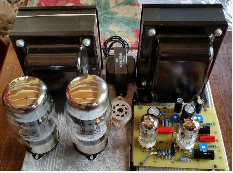
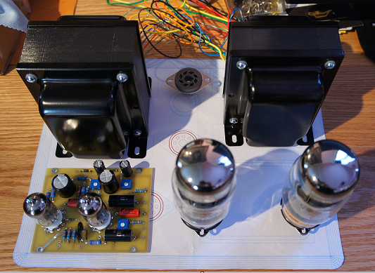
Any room to put the choke inside? Less clutter up top, and that would certainly give the transformers room to breathe.
My transformers are pretty tight, but never had any issues. Spacing is pretty much identical to a stock ST120 if I remember right.

Then again, they DO look like they fit the 4" center to center rule - more like 5". Then again, yet again, that "rule" seems a bit arbitrary based on iron size. The ST120 has some pretty massive iron compared to a lot of amps.
Oh. And ya ... 5AR4's ain't what they used to be. The Chinese ones are downright scary - you can read by the nuclear glow on one of those. I have a sweet little Mullard that doesn't work as hard and drives the amp well. Even better, I went to a Mullard GZ37 big bottle that doesn't even break a sweat. Food for thought - those and the GZ33 are about the same size as a KT88, so plan your layout accordingly if you want to have that option later on.
Last edited by sKiZo on Wed Mar 04, 2015 6:45 pm; edited 2 times in total