Tim,( setting the pots for the line voltage ) What that mean? Dale
+11
nmchiefsfan
DarthBubba
zx
turbotoy
Maintarget
Cubdriver
corndog71
Bob Latino
Pat R.
sKiZo
GP49
15 posters
Proposed Mark III Layout

Dale Stevens- Posts : 206
Join date : 2014-07-06
Age : 75
Location : Loris, SC
- Post n°76
 Re: Proposed Mark III Layout

TN Allen- Posts : 167
Join date : 2013-01-01
- Post n°78
 Re: Proposed Mark III Layout
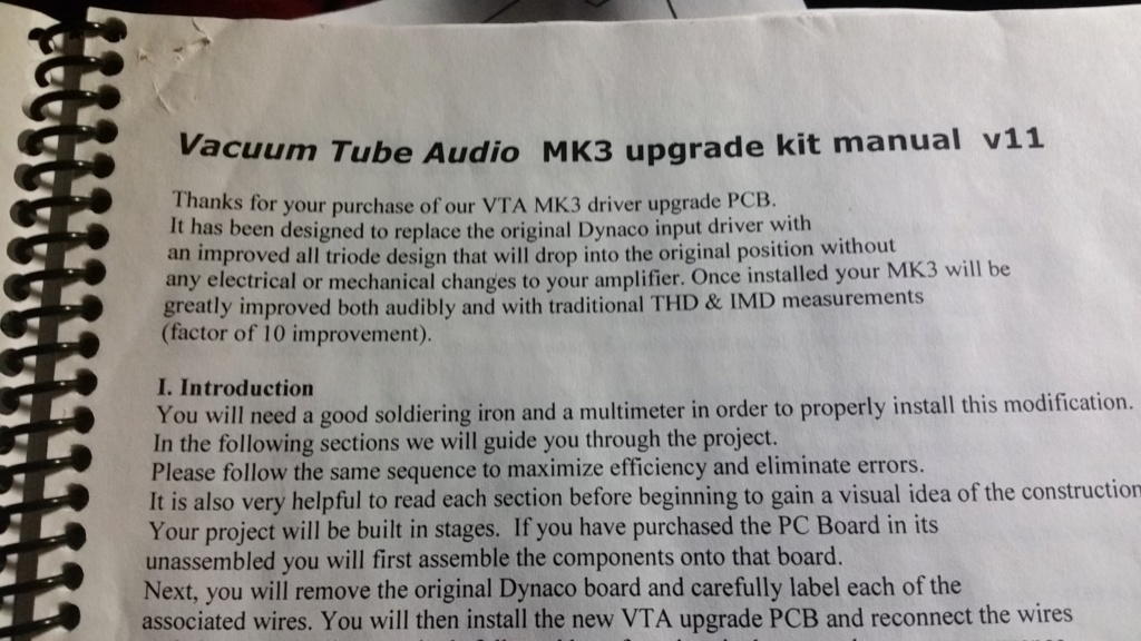
I apologize for the duplicates, I'll work on understanding inserting photos better. I included the second photo with the Vacuum Tube Audio...V11 to identify the instructions. The instructions are from several years ago, and as I recall came with the upgrade PCB. I've been working on this project seceral years.

TN Allen- Posts : 167
Join date : 2013-01-01
- Post n°79
 Re: Proposed Mark III Layout
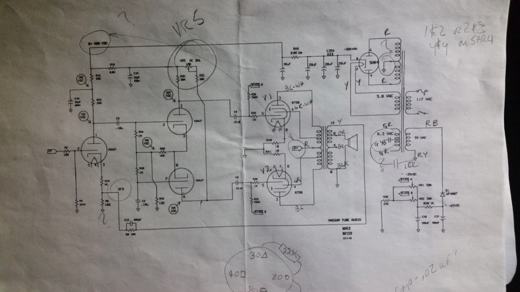
It appears the current version of the VTA Mark lll PCB does not have the extra potentiometer, the "AC Balance pots", VR5 mentioned in the instructions. Perhaps I'll contact Mr. Motram.

Bob Latino- Admin
- Posts : 3276
Join date : 2008-11-26
Location : Massachusetts
- Post n°80
 Re: Proposed Mark III Layout
TN Allen wrote:It appears the current version of the VTA Mark lll PCB does not have the extra potentiometer, the "AC Balance pots", VR5 mentioned in the instructions. Perhaps I'll contact Mr. Motram.
There is no AC balance control on the newer version of the VTA Mark III driver board that we have been using since 2012. That schematic that you show is for the pre 2012 VTA Mark III driver circuit.
Bob

TN Allen- Posts : 167
Join date : 2013-01-01
- Post n°81
 Re: Proposed Mark III Layout
That's the version I have. I started this project quite a while ago, the photos are from the instructions that came with the PCB kit from Mr. Motram. I suppose I should do these projects more quickly, but I really wasn't in a hurry. The PCB has the extra potentiometer.
I assume I should be concerned about the PS transformer temperature, it's just uncomforatble to touch for more than 30 seconds or so. Is it likely this is caused by using the SS rectifier? I think I read on one of the threads in this forum that the SS rectifiers may cause the amplifier to run a bit warm.
I assume I should be concerned about the PS transformer temperature, it's just uncomforatble to touch for more than 30 seconds or so. Is it likely this is caused by using the SS rectifier? I think I read on one of the threads in this forum that the SS rectifiers may cause the amplifier to run a bit warm.

TN Allen- Posts : 167
Join date : 2013-01-01
- Post n°82
 Re: Proposed Mark III Layout
I started this thread March 3, 2015. I probably bought the Mark 3 PCB kit from Mr. Motram about that time. Perhaps he sold me old stock because I wanted only one kit, as I intended to do only 1 amplifier?
» Poor man's solid state replacement rectifier for Dynaco ST-70, Mark II, Mark III or Mark IV
» Run your Dynaco ST-70, Mark II, Mark III or Mark IV in TRIODE MODE - photo
» ST-70, Mark II, Mark III and Mark IV - to check your date of manufacture
» Newly proposed VTA Lirpaloof M-500 monoblock amp - chassis photo ..
» Dynakit Mark 3 cage and Dynaco Mark 2 chassis and bottom cover wanted
» Run your Dynaco ST-70, Mark II, Mark III or Mark IV in TRIODE MODE - photo
» ST-70, Mark II, Mark III and Mark IV - to check your date of manufacture
» Newly proposed VTA Lirpaloof M-500 monoblock amp - chassis photo ..
» Dynakit Mark 3 cage and Dynaco Mark 2 chassis and bottom cover wanted


