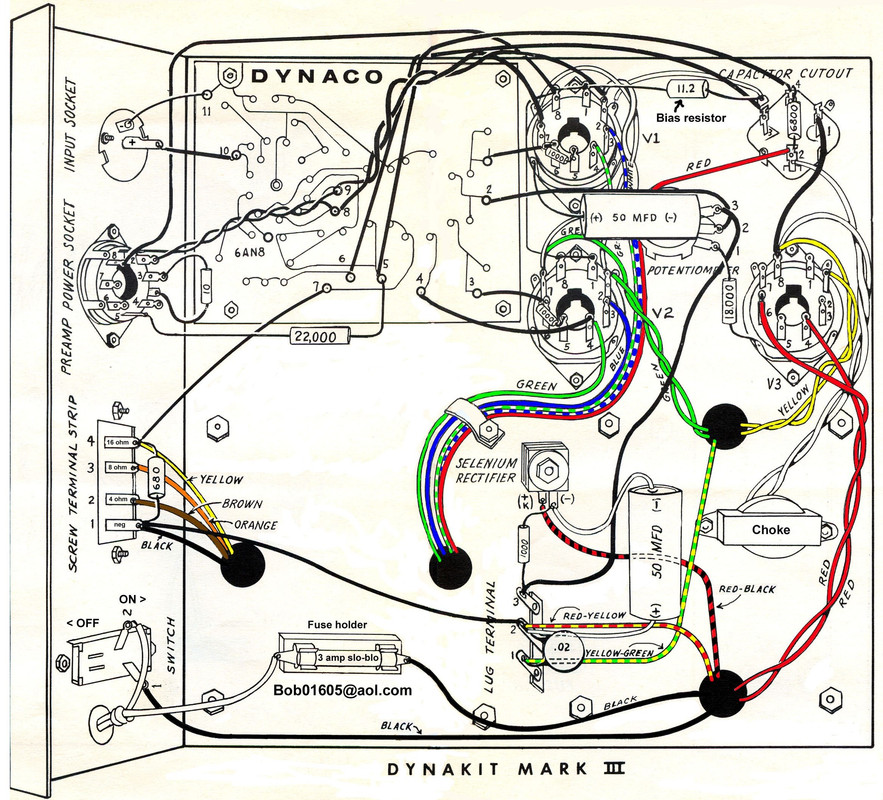
The Dynaco Tube Audio Forum

Would you like to react to this message? Create an account in a few clicks or log in to continue.
The Dynaco Tube Audio Forum

Dedicated to the restoration and preservation of all original Dynaco tube audio equipment - Customer support for Tubes4hifi VTA tube amp and preamp kits and all Dynakitparts.com products


+11
nmchiefsfan
DarthBubba
zx
turbotoy
Maintarget
Cubdriver
corndog71
Bob Latino
Pat R.
sKiZo
GP49
15 posters

    Proposed Mark III Layout

    avatar
    TN Allen


    Posts : 164
    Join date : 2013-01-01

    Proposed Mark III Layout - Page 3 Empty Re: Proposed Mark III Layout

    Post by TN Allen Sun Mar 22, 2015 11:41 am

    MontanaWay wrote:
    TN Allen wrote:Before looking more carefully at the Tubes4hifi MK3 photos and noticing the quad capacitor is 80-40-30-20, I bought a quad capacitor similar to what was used in the original MK3, 30-20-20-20. I'm wondering What advantage the 80 & etc capacitor provides over the original?

    a lot of components used in the original Dynaco amps as well as preamps were a compromise, mainly based on cost savings. The 30-20-20-20 is probably absolute minimum. Going somewhat higher, ie 80-40-30-20 gives the amp more 'stored energy', having to rely less just on the transformer to power the unit.
    Of course, having said that, there is a limit too, going to high is no good either. I would NOT use the 30-20-20-20 in this amp, so you'd be better of getting the 80-40-30-20, get the higher voltage unit too, costs a but more, but gives you that margin, especially during power up!

    MontanaWay,

    Thanks. This one: http://www.dynakitparts.com/dynakit-products/capacitors/MULTI-ELECTROLYTIC-C
    avatar
    Guest
    Guest


    Proposed Mark III Layout - Page 3 Empty Re: Proposed Mark III Layout

    Post by Guest Sun Mar 22, 2015 11:43 am

    TN Allen wrote:
    MontanaWay wrote:
    TN Allen wrote:Before looking more carefully at the Tubes4hifi MK3 photos and noticing the quad capacitor is 80-40-30-20, I bought a quad capacitor similar to what was used in the original MK3, 30-20-20-20. I'm wondering What advantage the 80 & etc capacitor provides over the original?

    a lot of components used in the original Dynaco amps as well as preamps were a compromise, mainly based on cost savings. The 30-20-20-20 is probably absolute minimum. Going somewhat higher, ie 80-40-30-20 gives the amp more 'stored energy', having to rely less just on the transformer to power the unit.
    Of course, having said that, there is a limit too, going to high is no good either. I would NOT use the 30-20-20-20 in this amp, so you'd be better of getting the 80-40-30-20, get the higher voltage unit too, costs a but more, but gives you that margin, especially during power up!

    MontanaWay,

    Thanks. This one:     http://www.dynakitparts.com/dynakit-products/capacitors/MULTI-ELECTROLYTIC-C

    yup, thats the animal! Smile cheers
    avatar
    TN Allen


    Posts : 164
    Join date : 2013-01-01

    Proposed Mark III Layout - Page 3 Empty Re: Proposed Mark III Layout

    Post by TN Allen Sun Mar 22, 2015 12:15 pm

    Thanks again, tna
    avatar
    TN Allen


    Posts : 164
    Join date : 2013-01-01

    Proposed Mark III Layout - Page 3 Empty Re: Proposed Mark III Layout

    Post by TN Allen Mon Apr 06, 2015 9:22 am

    I have a few more questions before I start making the layout and parts permanent. I'd appreciate any responses.

    sKiZo suggested that if I might want to use a GZ37 in the future, and that I should leave enough space for this larger tube. Would the GZ37 be suitable for the mono amp? At around $150 from TubeDepot, I might pass on it, or wait to use it in another stereo amp.

    If I want to eliminate the 5AR4, and a solid state rectifier in the tube socket, could someone recommend a circuit for a hardwired SS rectifier.

    Can the quad-capacitor be located inside the chassis?

    The tube spacing remains a dilemma, looking at the original design, and various other KT88 amp designs, spacing is close, really close in some cases. Is there evidence this does require replacing tubes more frequently?

    I checked the temperature half-way between the EL34s on the ST70, it's about 98-100F, close to the surface 180F, and between the output transformer and tube about 80F. Extrapolating from these temperatures, would spacing at 1/4-1/2 the distance be a significant problem? I realize the heat would dissipate more slowly with closer spacing, but wonder how much this would affect tube life and performance?

    Here are two photos of the tube socket pockets I'll probably mill in either Corian, or the copper-nickel plate. The only drawback to the Cu-Ni is that the top plate would way about 10lbs, the Corian only 2. I do like the look of the Cu-Ni, but would need a wheel barrow to move it around.Proposed Mark III Layout - Page 3 17709a2026e86fe1cba0d686cf4da8af
    Proposed Mark III Layout - Page 3 7454e7278dc831e012ce5e5ba00e944a
    corndog71
    corndog71


    Posts : 840
    Join date : 2013-03-19
    Location : It can get windy here

    Proposed Mark III Layout - Page 3 Empty Re: Proposed Mark III Layout

    Post by corndog71 Mon Apr 06, 2015 11:35 am

    I think this is one of those areas that you just have to make the call yourself. I've seen a lot of both instances (close vs far spacing) to think it's more of an aesthetic choice.

    So be creative. Make it look how you want.

    A simple solid state solution is to use a pair of UF4007 diodes with each diode's non-banded end going to one of the PT red leads. The banded ends come together and start the B+ to the first power supply cap.

    Proposed Mark III Layout - Page 3 Diode-rectifier-full-wave-centre-tapped-transformer
    sKiZo
    sKiZo


    Posts : 1530
    Join date : 2013-04-01
    Location : Michigan USA

    Proposed Mark III Layout - Page 3 Empty Re: Proposed Mark III Layout

    Post by sKiZo Mon Apr 06, 2015 3:46 pm

    TN Allen wrote:sKiZo suggested that if I might want to use a GZ37 in the future, and that I should leave enough space for this larger tube. Would the GZ37 be suitable for the mono amp? At around $150 from TubeDepot, I might pass on it, or wait to use it in another stereo amp.

    I got a NOS for $99 (Canadian military markings) and also got a good used 1950's Mullard for about the same. Consider that they may be the last rectifiers you need to buy as they're built strong, and also that you'll not brown out when driving them hard - always a possibility with a GZ34. Then again, the WZ68 copper cap is strong as well and a whole lot less. Your call ... I just like the big bottles. I'm also firmly convinced they sound better.

    Can the quad-capacitor be located inside the chassis?  

    Yup ... and seeing as how a pic is worth a thousand words ...

    Proposed Mark III Layout - Page 3 Left-choke

    The mounting strap is just some flashing tin doubled up and wrapped around the can. How well the case is grounded can make a big difference in how quiet the amp is. You can get a real tight fit if you're careful. I might look into changing out to a wider strap with a dual point mounting and add dielectric grease for improved ground sometime down the road. No rush as there's no noise now, but it couldn't hurt, and I've got a couple other tweaks I want to do anyway.

    The tube spacing remains a dilemma, looking at the original design, and various other KT88 amp designs, spacing is close, really close in some cases. Is there evidence this does require replacing tubes more frequently?

    Heat is a killer. How much heat you get depends on ventilation and how hard you drive the tubes. Add some vents around each tube ...

    Proposed Mark III Layout - Page 3 Socket-pads2

    That creates a chimney effect that will draw cooler air up from underneath IF you allow for adequate internal venting as well - air's gotta come from someplace.

    avatar
    TN Allen


    Posts : 164
    Join date : 2013-01-01

    Proposed Mark III Layout - Page 3 Empty Re: Proposed Mark III Layout

    Post by TN Allen Wed May 06, 2015 10:59 am

    I've made some progress on this amp project recently. The plate is heavy, but not nearly as heavy as the transformers. I milled one in Copper-Nickel, another in 1/2" Corian. But will probably use the first. Micro-phonics should not be a problem.

    Proposed Mark III Layout - Page 3 06ac0122b8651da4a17e271fd75b34c7

    In locating the sockets for the KT 88s, I can have these with both of the pin orientation slots(is there a better term for these?) facing left, right or opposing. In other words, the tubes can be in the same orientation, or mirrored. Is the tube orientation critical?
    avatar
    DarthBubba


    Posts : 88
    Join date : 2012-05-05

    Proposed Mark III Layout - Page 3 Empty Re: Proposed Mark III Layout

    Post by DarthBubba Wed May 06, 2015 5:45 pm

    TN Allen wrote:Here are two photos of a revised layout, ...  but would like to keep the layout reasonably compact. I'd appreciate any further comments or suggestions.

    Proposed Mark III Layout - Page 3 2431437f7467dc82b77d273aae6efb90

    I'd swap the rectifier and quad-cap locations.  That would give the rectifier, solid state or hollow-state, more breathing room.

    Just my $0.02, and worth every penny you paid.
    avatar
    nmchiefsfan


    Posts : 77
    Join date : 2012-03-21

    Proposed Mark III Layout - Page 3 Empty Re: Proposed Mark III Layout

    Post by nmchiefsfan Wed May 06, 2015 10:38 pm

    If you are going to locate the quad cap underneath, would it not be easier to use discreet components?
    avatar
    TN Allen


    Posts : 164
    Join date : 2013-01-01

    Proposed Mark III Layout - Page 3 Empty Re: Proposed Mark III Layout

    Post by TN Allen Sat May 09, 2015 10:35 am

    nmchiefsfan wrote:If you are going to locate the quad cap underneath, would it not be easier to use discreet components?

    I already have the quad capacitor and other parts, so, I think I'll use these.
    avatar
    TN Allen


    Posts : 164
    Join date : 2013-01-01

    Proposed Mark III Layout - Page 3 Empty Re: Proposed Mark III Layout

    Post by TN Allen Sat May 09, 2015 11:04 am

    Before I make any of the underside of the Mark 3 amp permanent, I wondered if anyone has alternate suggestions I should consider or use. The first photo is with everything in place, but loose, the second shows the parts removed that cover the holes for the transformer wires. These parts would be set off the plate far enough to run the transformer wires without crowding.

    Also, is there a place I can connect the 2.1-3.5 V LED, preferably on the PCB? Thanks for any suggestions or concerns, I appreciate the assistance.

    Proposed Mark III Layout - Page 3 F5745e4faa059ea2e09f1a712a7e583c

    Proposed Mark III Layout - Page 3 A796f4982956a651f84ecee9db2e7f9a
    avatar
    TN Allen


    Posts : 164
    Join date : 2013-01-01

    Proposed Mark III Layout - Page 3 Empty Re: Proposed Mark III Layout

    Post by TN Allen Sun Jan 24, 2016 6:48 pm

    After several months on other projects, I'm ready to wire this amp. I have the Dynaco manual download, the supplemental sheet for the quad cap. from Dynakit Parts, and the instructions for the tubes4hifi PCB. Are there other schematics I might download and use?
    avatar
    TN Allen


    Posts : 164
    Join date : 2013-01-01

    Proposed Mark III Layout - Page 3 Empty Re: Proposed Mark III Layout

    Post by TN Allen Sun Feb 14, 2016 1:08 pm

    I started with the PCB from VTA and transformers from Triode, the quad-capacitor from Dynakit Parts, consequently I don't have an old MKIII to follow for the wiring, but have the VTA MKIII instructions and the original Dynaco Instructions download. Rather than risk real damage to what I have, and possible electrocution, I thought I'd ask for help, and will appreciate any offered.

    I think I have most of this figured out, the connections from the transformers to the tube sockets seem clear, but I may well not have the rest of the connections correct. My questions regarding these are:

    1. Does the Red-Black wire from the Power Transformer connect to the Bias eyelet on the VTA PCB?

    2.The quad-capacitor pins are designated as 1-4 on the VTA MKIII sheet, how do 1-4 relate to the square, triangle, half circle and circle, or the capacitor values?

    3. Which of the tubes should be designated V1 on the VTA sheet? I assume this is important for connecting to the V3 & V4 OUT eyelets on the PCB.

    4. Is the extra wire from the 16 ohm Output transformer to connect to the NFB eyelet on the PCB.

    5. Can the instructions for assembling a new MKIII using the VTA PCB be downloaded, if so, where?

    Here is a link to a Flickr photo of the amp so far:  https://www.flickr.com/photos/68227271@N04/25024347595/in/datetaken/

    I left the choke out, but it fits in adjacent to the Output connections. As I wrote above, any suggestions will be appreciated.
    avatar
    TN Allen


    Posts : 164
    Join date : 2013-01-01

    Proposed Mark III Layout - Page 3 Empty Re: Proposed Mark III Layout

    Post by TN Allen Sat Nov 24, 2018 10:22 am

    I decided to return to this project, it's been about 3 years, and still have questions. Would anyone know of instructions or a wiring diagram for new Mark llls using Trident Mark lll replacement transformers and the VTA MK3 upgrade PCB? I'm primarily concerned about transformer color code changes. Thanks for any assistance.
    avatar
    TN Allen


    Posts : 164
    Join date : 2013-01-01

    Proposed Mark III Layout - Page 3 Empty Re: Proposed Mark III Layout

    Post by TN Allen Sun Mar 10, 2019 2:51 pm

    Would anyone know what voltage rating for the .02uF for the small disc shaped capacitor soldered to the terminal strip between the red-yellow and yellow-green wires.

    Also, the instructions I have show the yellow wire from the output transformer connected to the NFB eyelet on the new Tubes4HiFi PCB, I think I have this correct. But this seems to eliminate the 16 Ohm output. If possible, I'd like to retain the 16 Ohm output. Is there a way to do this?

    Thanks in advance for any suggestions.
    peterh
    peterh


    Posts : 1836
    Join date : 2012-12-25
    Location : gothenburg, sweden

    Proposed Mark III Layout - Page 3 Empty Re: Proposed Mark III Layout

    Post by peterh Sun Mar 10, 2019 3:21 pm

    TN Allen wrote:Would anyone know what voltage rating for the .02uF for the small disc shaped capacitor soldered to the terminal strip between the red-yellow and yellow-green wires.

    Also, the instructions I have show the yellow wire from the output transformer connected to the NFB eyelet on the new Tubes4HiFi PCB, I think I have this correct. But this seems to eliminate the 16 Ohm output. If possible, I'd like to retain the 16 Ohm output. Is there a way to do this?

    Thanks in advance for any suggestions.
    The 0.02 cap :
    it's a hum-dinger for the filaments. Voltage 50V will do!

    Today one uses a resistor, say 100ohm, to keep the filaments at a defined level.
    But,
    The yellow wire IS the 16 ohm tap. Connect it to the output then continue with a wire to the
    PCB.


    Last edited by peterh on Sun Mar 10, 2019 3:46 pm; edited 2 times in total (Reason for editing : cap discovery)
    avatar
    TN Allen


    Posts : 164
    Join date : 2013-01-01

    Proposed Mark III Layout - Page 3 Empty Re: Proposed Mark III Layout

    Post by TN Allen Sun Mar 10, 2019 3:46 pm

    Thank you!
    avatar
    TN Allen


    Posts : 164
    Join date : 2013-01-01

    Proposed Mark III Layout - Page 3 Empty Re: Proposed Mark III Layout

    Post by TN Allen Thu Nov 28, 2019 12:47 pm

    I may yet finish this project. It is wired, though I overlooked the 2 1K resistors on pins 5&6 on the KT88 sockets. I don't know how I overlooked them, but did. I have 1K 1 Watt resistors.

    Unfortunately I tried the amplifier without these, although only so far as checking to see if the filaments had current, which they did, and then with the rectifier and KT88 tubes in place and powered, but without the 12AU7 tubes in their sockets. The 3Amp fuse blew, hopefully avoiding any other damage.

    I plan to solder in the 1K resistors, and add 4007 diodes to the rectifier socket, even though I'm using a SS rectifier substitute for the 5AR4.

    I suspect there may be damage beyond the blown fuse. Would anyone have any suggestions for what I should check for damage? And, before soldering the resistors and diodes in place, how should I safely dissipate any residual current in the quad capacitor?

    This has been a good project, I've learned quite a bit doing it. There are quite a few things I'd do differently were I to do another MK lll, but nonetheless it's been a good learning experience.
    peterh
    peterh


    Posts : 1836
    Join date : 2012-12-25
    Location : gothenburg, sweden

    Proposed Mark III Layout - Page 3 Empty Re: Proposed Mark III Layout

    Post by peterh Thu Nov 28, 2019 1:00 pm

    TN Allen wrote:I may yet finish this project. It is wired, though I overlooked the 2 1K resistors on pins 5&6 on the KT88 sockets. I don't know how I overlooked them, but did. I have 1K 1 Watt resistors.

    Unfortunately I tried the amplifier without these, although only so far as checking to see if the filaments had current, which they did, and then with the rectifier and KT88 tubes in place and powered, but without the 12AU7 tubes in their sockets. The 3Amp fuse blew, hopefully avoiding any other damage.

    I plan to solder in the 1K resistors, and add 4007 diodes to the rectifier socket, even though I'm using a SS rectifier substitute for the 5AR4.

    I suspect there may be damage beyond the blown fuse. Would anyone have any suggestions for what I should check for damage? And, before soldering the resistors and diodes in place, how should I safely dissipate any residual current in the quad capacitor?

    This has been a good project, I've learned quite a bit doing it. There are quite a few things I'd do differently were I to do another MK lll, but nonetheless it's been a good learning experience.
    If the 1k resistor between pin 6 and 5 is missing the tubes will have no bias and will conduct
    heavily. As the fuse blew i do not suspect any fatal damage. Mount the resistor, and with kt88 out
    and rectifier tube also out adjust the bias pot to get maximum negative voltage on pin 5 and 6

    Turn off, install kt88 and rectifier, add load to the speaker outputs ( speaker or power resistor) then
    turn on and adjust the bias as per the manual.
    avatar
    stewdan


    Posts : 231
    Join date : 2010-03-07
    Age : 85
    Location : Houston Texas

    Proposed Mark III Layout - Page 3 Empty Re: Proposed Mark III Layout

    Post by stewdan Fri Nov 29, 2019 12:25 am

    TN Allen ..... Bob Latino has posted on the Web a colored wiring diagram for the Mark III which has all the colors of the Transformer Wirings and might be of use to you?!

    Do a Google Search for "Latino Mark III Wiring" and you will pull it up.
    Bob Latino
    Bob Latino
    Admin


    Posts : 3263
    Join date : 2008-11-26
    Location : Massachusetts

    Proposed Mark III Layout - Page 3 Empty Re: Proposed Mark III Layout

    Post by Bob Latino Fri Nov 29, 2019 8:38 am

    stewdan wrote:TN Allen ..... Bob Latino has posted on the Web a colored wiring diagram for the Mark III which has all the colors of the Transformer Wirings and might be of use to you?!

    Do a Google Search for "Latino Mark III Wiring" and you will pull it up.

    That wiring diagram for the Dynaco Mark III is below ..

    Bob


    Proposed Mark III Layout - Page 3 Dynaco-Mark-III-pictorial
    avatar
    TN Allen


    Posts : 164
    Join date : 2013-01-01

    Proposed Mark III Layout - Page 3 Empty Re: Proposed Mark III Layout

    Post by TN Allen Fri Nov 29, 2019 5:18 pm

    Thank you for the assistance. I soldered in the missing resistors and added the diodes. One lead from the input had broken, but with that replaced the Mark lll works, and sounds quite nice running direct between an old CD player and a speaker cabinet I did a few years ago. I'll try posting a photo later.
    avatar
    TN Allen


    Posts : 164
    Join date : 2013-01-01

    Proposed Mark III Layout - Page 3 Empty Re: Proposed Mark III Layout

    Post by TN Allen Fri Nov 29, 2019 9:29 pm

    Here is a photo of the Mark lll, which sounds quite promising. The 2 preamps I tried with it were disappointing. One is an updated PAS3X, the other an SP9, as I recall. The CD player direct into the amplifier was flawed, but promising. I may build a mono speaker system specifically to compliment this amplifier. Thank you again to all who offered assistance and suggestions, I appreciate the generosity and congeniality of the forum. Proposed Mark III Layout - Page 3 15750711Proposed Mark III Layout - Page 3 15750711
    avatar
    TN Allen


    Posts : 164
    Join date : 2013-01-01

    Proposed Mark III Layout - Page 3 Empty Re: Proposed Mark III Layout

    Post by TN Allen Sat Dec 07, 2019 2:17 pm

    I have a few more questions about the line voltage adjustment and bias. First though, this is a very nice mono amplifier, it has an intimate, pleasant sound playing digital files or records. I've adjusted tone using a MiniDSP for the turntable, and a graphic equalizer playing digital files. I can't quite imagine a speaker combination yet for it, but presently it does well through a T/L using a Peerless NE225W-04 woofer, and a Peerless ring radiator, which is in a 2 3/4" deep X 11" dia. round waveguide.

    The questions regard setting the potentiometer(s) for the AC line voltage and bias potentiometers for the KT88s. I set the KT88 bias at .498-.501V, these fluctuated slightly, and I had the potentiometers at their extreme CCW position, I think I have this correct, that is at the lowest bias setting. I haven't tried adjusting the AC line voltage yet.

    One concern is that the PS transformer is just warm enough to be uncomfortable to touch. I can hold my hand on it, but it is slightly uncomfortable. The output transformer remains only slightly warm, perhaps a degree or two above body temperature.

    I live in Downeast Maine, our grid is old and fails frequently, and I doubt the voltage is stable, so I decided to use a 5AR4 SS rectifier rather than a tube. Perhaps our line current and the SS rectifier partially account for the heat? The rectifier is from TubeDepot, I'll find a link and post it shortly.
    avatar
    TN Allen


    Posts : 164
    Join date : 2013-01-01

    Proposed Mark III Layout - Page 3 Empty Re: Proposed Mark III Layout

    Post by TN Allen Sat Dec 07, 2019 2:21 pm

    The SS rectifier link from TubeDepot is:
    https://www.tubedepot.com/products/solid-state-rectifier
    Thank you all again for the assistance with this project.

    Sponsored content


    Proposed Mark III Layout - Page 3 Empty Re: Proposed Mark III Layout

    Post by Sponsored content


      Current date/time is Sun May 19, 2024 11:11 am