The Dynaco Tube Audio Forum

Would you like to react to this message? Create an account in a few clicks or log in to continue.
The Dynaco Tube Audio Forum

Dedicated to the restoration and preservation of all original Dynaco tube audio equipment - Customer support for Tubes4hifi VTA tube amp and preamp kits and all Dynakitparts.com products


+11
nmchiefsfan
DarthBubba
zx
turbotoy
Maintarget
Cubdriver
corndog71
Bob Latino
Pat R.
sKiZo
GP49
15 posters

    Proposed Mark III Layout

    Pat R.
    Pat R.


    Posts : 57
    Join date : 2015-02-26
    Location : SE Pennsylvania

    Proposed Mark III Layout - Page 2 Empty Re: Proposed Mark III Layout

    Post by Pat R. Sat Mar 07, 2015 8:53 am

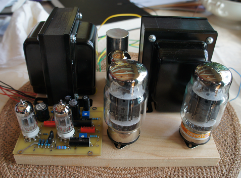
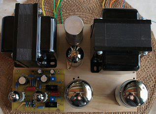
    sKizo, on the photos you posted the first top plate is flat with bias pots in a different spot..  and then the Monarch Limited has a bent down front plate some minor changes.. is the first one yours too? Or is that something you copied your Monarch from.. I like features of both.. this is why I ask..

    Also wondering if you have a PDF of the design? Having access to the sizes for holes and such would make design a lot easier. Meters are always a very cool touch!! I could see doing something like that, but as I said I like canned xformers and I might consider doing something that Mc is now doing.. That is adding LED's to the tube sockets to give the tubes a cool glow. I think they use green.. blue might be nice..


    Also on the ST 70 I just built I opted for the original style speaker terminals as I wanted the flexibility of using 4/8/16 ohm speakers.. I could see where on a custom app like this I could make room for more binding posts of a modern type and still have that flexibility.
    Pat R.
    Pat R.


    Posts : 57
    Join date : 2015-02-26
    Location : SE Pennsylvania

    Proposed Mark III Layout - Page 2 Empty Re: Proposed Mark III Layout

    Post by Pat R. Sat Mar 07, 2015 10:04 am

    Pat R. wrote:
    TN Allen wrote:Pat R.,

    They are on a website www.vt4c.com

    I'm using a phone and haven't figured out how to provide a direct link.

    I also saw many available via ebay, however, they were more expensive.

    I think they would be very attractive.

    Thanks for the site.. it's pretty big and I'll have to look around. If you get to a computer and can send a link to the can page that would be great.. meanwhile I'll keep looking.

    I found the cans this morning.. and after looking at them. There is no doubt in my mind when I build my next project I'm going to hide the transformers in those cans.. I think I like the aluminum and steel cans.. the alum would conduct heat better and I'd order the large to leave a bit of room around the transformers..

    Also they look reasonably priced at an average of $15 US each.
    Thanks for the site!
    Bob Latino
    Bob Latino
    Admin


    Posts : 3263
    Join date : 2008-11-26
    Location : Massachusetts

    Proposed Mark III Layout - Page 2 Empty Re: Proposed Mark III Layout

    Post by Bob Latino Sat Mar 07, 2015 10:39 am

    Pat R. wrote: I think I like the aluminum and steel cans.. the alum would conduct heat better and I'd order the large to leave a bit of room around the transformers..

    Pat,

    Aluminum does not conduct heat better than steel (iron) ... Steel (iron) is a better conductor of heat than aluminum and would conduct heat away from the transformer better. How well a material conducts heat is related to its "specific heat". The specific heat of iron (similar to steel) is about 1/2 of what aluminum is. Items with low specific heats heat up AND cool down quickly. Items with high specific heats require a lot of energy to heat up but "hold on to the heat" for a longer time.

    Bob
    avatar
    TN Allen


    Posts : 164
    Join date : 2013-01-01

    Proposed Mark III Layout - Page 2 Empty Re: Proposed Mark III Layout

    Post by TN Allen Sat Mar 07, 2015 10:49 am

    Pat R.,

    Glad you found them, I was about to send the link, when I saw your post. tna
    Pat R.
    Pat R.


    Posts : 57
    Join date : 2015-02-26
    Location : SE Pennsylvania

    Proposed Mark III Layout - Page 2 Empty Re: Proposed Mark III Layout

    Post by Pat R. Sat Mar 07, 2015 12:52 pm

    Bob Latino wrote:
    Pat R. wrote: I think I like the aluminum and steel cans.. the alum would conduct heat better and I'd order the large to leave a bit of room around the transformers..

    Pat,

    Aluminum does not conduct heat better than steel (iron) ... Steel (iron) is a better conductor of heat than aluminum and would conduct heat away from the transformer better. How well a material conducts heat is related to its "specific heat". The specific heat of iron (similar to steel) is about 1/2 of what aluminum is. Items with low specific heats heat up AND cool down quickly. Items with high specific heats require a lot of energy to heat up but "hold on to the heat" for a longer time.

    Bob

    Thanks for clearing that up!.. I was under the impression that alum conducted heat better since it seems to heat up fast.. ie my cast iron skillets that take a long time to heat up and hold the heat.
    Maintarget
    Maintarget


    Posts : 227
    Join date : 2013-02-10

    Proposed Mark III Layout - Page 2 Empty Re: Proposed Mark III Layout

    Post by Maintarget Sat Mar 07, 2015 1:14 pm

    I'm so confused..........

    The following table was compiled from data available in the CRC Handbook of Chemistry and Physics. All values are for materials at room temperature (298K), except where indicated.

    Thermal conductivity of other common materials:

    Material Thermal conductivity (298K)
    W/mK
    Diamond 895-2300
    Silver 429
    Copper 386
    Gold 317
    Aluminium 237
    Brass 120
    Platinum 71.6
    Iron 80.2
    Lead 35.3
    Quartz (273K) 6.8-12
    Glass 1.35
    Wood 0.04 (balsa) - 0.35 (fir)
    Styrofoam 0.033
    Wool 0.04
    Silica aerogel 0.017
    Air (100 kPa) 0.0262
    Water 0.6062
    Ice (273K) 2.2
    Mercury 8.514


    Thermal conductivity changes with temperature. For most materials it decreases slightly as the temperature rises
    Source:
    http://en.allexperts.com/q/Metallurgy-22...
    avatar
    turbotoy


    Posts : 48
    Join date : 2012-04-15

    Proposed Mark III Layout - Page 2 Empty Re: Proposed Mark III Layout

    Post by turbotoy Sat Mar 07, 2015 1:24 pm

    Bob Latino wrote:
    Pat R. wrote: I think I like the aluminum and steel cans.. the alum would conduct heat better and I'd order the large to leave a bit of room around the transformers..

    Pat,

    Aluminum does not conduct heat better than steel (iron) ... Steel (iron) is a better conductor of heat than aluminum and would conduct heat away from the transformer better. How well a material conducts heat is related to its "specific heat". The specific heat of iron (similar to steel) is about 1/2 of what aluminum is. Items with low specific heats heat up AND cool down quickly. Items with high specific heats require a lot of energy to heat up but "hold on to the heat" for a longer time.

    Bob

    Sorry Bob, as someone who works in the field of heat transfer, I need to correct you. The thermal conductivity of aluminum is ~140 BTU/hr/ft/degF. The thermal conductivity of carbon steel is ~30 BTU/hr/ft/degF. What you said about specific heat (units of BTU/lbm/degF) is correct, but is also irrelevant to thermal conductivity. As far as steady-state heat transfer is concerned, which is what we care about for this application, the specific heat of the material is rather irrelevant and would only affect the transient response.
    Pat R.
    Pat R.


    Posts : 57
    Join date : 2015-02-26
    Location : SE Pennsylvania

    Proposed Mark III Layout - Page 2 Empty Re: Proposed Mark III Layout

    Post by Pat R. Sat Mar 07, 2015 1:56 pm

    Ok if you guys are confused I'm really confused.. I'm not into physics I just always assumed that something that heats up faster and cools down faster would be better at removing heat. In cooking.. the cast iron skillet is better for cooking certain things because it holds the heat. To me in common sense terms says if it holds the heat, it doesn't release the heat.. which also in my head says.. it is not good for wicking away the heat or cooling..

    So in plain english so a dummy as far as physics goes..

    Would an Aluminum can or a Steel Can be better at removing the heat given off by a transformer.. ?

    avatar
    zx


    Posts : 205
    Join date : 2011-08-05

    Proposed Mark III Layout - Page 2 Empty Re: Proposed Mark III Layout

    Post by zx Sat Mar 07, 2015 2:56 pm

    Never seen a Steel transistor heat sink!....but some must have been made..
    .But steel is used for a RF faraday shiled or cage....Steel is beter than aluminum..  steel is used  on tranfourmers.....I was told at one time that Steel was beeter sounding than aluminum for chassie...but thin I got my hhshott an Krell peaces....there all aluminum....gofig
    Dan Dagostino of krell fame ....has new amps that he can get class A sound out of AB amps setup with all copper heatsinks....that do sound good.............but BIG $$$$$$$....hehe
    .Bob knows something we don't...........?


    Thanks Bob............
    avatar
    turbotoy


    Posts : 48
    Join date : 2012-04-15

    Proposed Mark III Layout - Page 2 Empty Re: Proposed Mark III Layout

    Post by turbotoy Sat Mar 07, 2015 3:26 pm

    Sorry, let me attempt to better explain what is physcially happening and answer your question.

    Forget about heating up and down, holding heat, etc. That thought process concerns the transient response of a system. During operation of an amplifier, we turn it on, the components warm up, and steady-state equilibrium is reached.

    Consider the space inside of the can to have a heat source due to the transformer. Heat will be removed from this internal space by flowing through the can thickness, and will be transferred to the environment from the outer surface of the can through convection and radiation. To keep the problem simple, let us assume that the outer surface of the can is at an equilibrium temperature of To, and the inside surface of the can is at Ti. In differential form, Fourier's Law of conduction states:

    q = -k(dT/dx)

    where:
    q is the heat transfer rate
    k is the thermal conductivity
    dT/dx is the temperature gradient through the thickness of the material

    In this case, x is the thickness of the can material. Now imagine that in the above equation, q is held constant. If k is increased, the temperature gradient, dT/dx is decreased. Assuming the outside of the can is at To, that means that as k is increased, Ti will be reduced and become closer to To. This ignores many other important aspects of the actual heat transfer process, but hopefully explains the concept of conduction.

    In practice, the material selected for the can will not affect the temperature of the transformer much. Why? The thickness of the can is relatively small, so the temperature gradient through the can thickness will be low. In other words, whether aluminum or steel, the inside surface of the can will be at close to the same temperature as the outside surface of the can. The color and surface roughness of the can, which affect the heat removed by radiation and convection, are likely more important parameters.

    So, aluminum would theoretically be the better material choice, but in practical terms it probably does not matter at all in this application.
    Bob Latino
    Bob Latino
    Admin


    Posts : 3263
    Join date : 2008-11-26
    Location : Massachusetts

    Proposed Mark III Layout - Page 2 Empty Re: Proposed Mark III Layout

    Post by Bob Latino Sat Mar 07, 2015 3:56 pm

    OK - I stand corrected. Aluminum does have the ability to absorb more heat than iron without changing its temperature because it has a higher specific heat. I was thinking in terms of > because iron has a lower specific heat than aluminum > if you place a kilogram of each material heated to the same temperature in the cooler outside environment then the iron will cool (get rid of the heat it is holding) at a quicker rate than the aluminum.

    Bob
    Pat R.
    Pat R.


    Posts : 57
    Join date : 2015-02-26
    Location : SE Pennsylvania

    Proposed Mark III Layout - Page 2 Empty Re: Proposed Mark III Layout

    Post by Pat R. Sat Mar 07, 2015 4:18 pm

    turbotoy wrote:Sorry, let me attempt to better explain what is physcially happening and answer your question.  

    Forget about heating up and down, holding heat, etc.  That thought process concerns the transient response of a system.  During operation of an amplifier, we turn it on, the components warm up, and steady-state equilibrium is reached.

    Consider the space inside of the can to have a heat source due to the transformer.  Heat will be removed from this internal space by flowing through the can thickness, and will be transferred to the environment from the outer surface of the can through convection and radiation.  To keep the problem simple, let us assume that the outer surface of the can is at an equilibrium temperature of To, and the inside surface of the can is at Ti.  In differential form, Fourier's Law of conduction states:

    q = -k(dT/dx)

    where:
    q is the heat transfer rate
    k is the thermal conductivity
    dT/dx is the temperature gradient through the thickness of the material

    In this case, x is the thickness of the can material.  Now imagine that in the above equation, q is held constant.  If k is increased, the temperature gradient, dT/dx is decreased.  Assuming the outside of the can is at To, that means that as k is increased, Ti will be reduced and become closer to To.  This ignores many other important aspects of the actual heat transfer process, but hopefully explains the concept of conduction.  

    In practice, the material selected for the can will not affect the temperature of the transformer much.  Why?  The thickness of the can is relatively small, so the temperature gradient through the can thickness will be low.  In other words, whether aluminum or steel, the inside surface of the can will be at close to the same temperature as the outside surface of the can.  The color and surface roughness of the can, which affect the heat removed by radiation and convection, are likely more important parameters.  

    So, aluminum would theoretically be the better material choice, but in practical terms it probably does not matter at all in this application.  

    Ok there's an answer I can sink (not heat) my teeth into..

    A ribbed aluminum can painted black?? lol..

    Thanks for clearing it up.
    avatar
    turbotoy


    Posts : 48
    Join date : 2012-04-15

    Proposed Mark III Layout - Page 2 Empty Re: Proposed Mark III Layout

    Post by turbotoy Sat Mar 07, 2015 4:31 pm

    Bob Latino wrote:Aluminum does have the ability to absorb more heat than iron without changing its temperature because it has a higher specific heat.
    Bob

    That it true, but there is one important thing to keep in mind, the density of aluminum is roughly 1/3rd that of steel. So, even though aluminum has a specific heat that is approximately twice that of steel, the "volumetric heat capacity" of steel is approximately 1.5 times that of aluminum. If we are talking about cans with the same thickness/volume, thinking about heat capacity in terms of volumetric heat capacity vice specific heat is more appropriate. In the fluid heat transfer world that I live in, it is generally easier to normalize heat capacity by mass vice volume, and that is why you usually see it tabulated that way.

    Note, all that increased specific heat will do is cause longer temperature rise and fall times. The steady-state temperatures reached do not depend on specific heat. Perhaps it would help to think of it in electrical terms like this:

    Thermal conductivity is similar to 1/resistance in a circuit
    Specific heat is similar to capacitance in a circuit.

    Hopefully I didn't derail this thread too much, and I am very much not trying to nit-pick, just clarify the engineering.
    avatar
    TN Allen


    Posts : 164
    Join date : 2013-01-01

    Proposed Mark III Layout - Page 2 Empty Re: Proposed Mark III Layout

    Post by TN Allen Sat Mar 07, 2015 5:33 pm

    The clarification is good from my perspective. Heat and unwanted inductance are both relevant to my request for suggestions on the layout.

    Would you have an idea how far apart the transformers need to be if positioned with the cores in a parallel plane, in order to avoid 60Hz. interference? I know the intensity of the magnetic field is based upon the square root of the distance apart, but would like to know more about the likelihood of interference if I were to position the transformers as they are in the photo. It's not that I doubt the advice offered regarding turning one transformer, rather that I'd like to understand the phenomenon more fully.
    sKiZo
    sKiZo


    Posts : 1530
    Join date : 2013-04-01
    Location : Michigan USA

    Proposed Mark III Layout - Page 2 Empty Re: Proposed Mark III Layout

    Post by sKiZo Sat Mar 07, 2015 6:11 pm

    Way I understand it ...

    All transformer windings have a certain amount of leakage. They're designed and spec'd so that any leakage in one winding will couple in another aligned winding - in the same transformer. This keeps efficiency and performance high. Put another transformer in the same plane close enough for interaction, and you've got a potential for coupling there as well - interaction that could degrade the performance of both. This interaction would decrease with distance, but still be there unless completely intercepted by a buffer of some sort. That's the primary reason for setting standard laminated units at 90 degrees to each other. In the case of an amp with a PT between two OT's, the PT becomes that buffer I mentioned.

    If you're dead set on symmetry, you might want to consider going toroidal ... those have very low stray magnetics. Or add the covers and deal with the potential heat issues.
    Pat R.
    Pat R.


    Posts : 57
    Join date : 2015-02-26
    Location : SE Pennsylvania

    Proposed Mark III Layout - Page 2 Empty Re: Proposed Mark III Layout

    Post by Pat R. Sat Mar 07, 2015 7:18 pm

    turbotoy wrote:
    Note, all that increased specific heat will do is cause longer temperature rise and fall times.  The steady-state temperatures reached do not depend on specific heat.  Perhaps it would help to think of it in electrical terms like this:

    Thermal conductivity is similar to 1/resistance in a circuit
    Specific heat is similar to capacitance in a circuit.

    Hopefully I didn't derail this thread too much, and I am very much not trying to nit-pick, just clarify the engineering.

    I don't think this is derailing the thread at all but I see it rather as very good information regarding design, function and aesthetics of the amps we choose to build.

    So if I'm reading this correctly and I only ask again so that us "lay persons" can understand this in basic english..

    The Can covers for the transformers will not really cause any troubles to the transformers.. once the temperature is reached the outside of the can will maintain the temperature of the transformer itself. I'm also guessing that the surface area of the can which will be much larger than the transformer to contain it would be a good thing. The material the can is made of will only determine how long after the unit is off that the can will hold the heat..

    So if the Transformer reaches 150 Degrees F then the can will reach 150 Degrees F and no more.. but the material it is made of will determine how fast it gets there and how fast it cools off after use..

    Am I getting this..
    avatar
    turbotoy


    Posts : 48
    Join date : 2012-04-15

    Proposed Mark III Layout - Page 2 Empty Re: Proposed Mark III Layout

    Post by turbotoy Sat Mar 07, 2015 8:22 pm

    TN Allen wrote:
    Would you have an idea how far apart the transformers need to be if positioned with the cores in a parallel plane, in order to avoid 60Hz. interference? I know the intensity of the magnetic field is based upon the square root of the distance apart, but would like to know more about the likelihood of interference if I were to position the transformers as they are in the photo. It's not that I doubt the advice offered regarding turning one transformer, rather that I'd like to understand the phenomenon more fully.

    Readily avaible literature on classical electromagnetism, Faraday, Maxwell, etc. would be the best place to start to gain an understanding of the phenomenon. Fortunately these days all that information is available in seconds, and can do a much better job of explaining things than I can. I will tell you that attempting to quantify the effect of orientation angle or spacing on induced voltage in the output transformer is possible, but would be very non-trivial. Really, any model would need to be validated by experiment.

    The better thing to do would be to just perform the experiment. The easiest way would be if you had an existing amp. You could then measure the induced voltage in the output transformer as a function of distance, angle, etc. from the power transformer. However, the crux of the problem is how much induced voltage is acceptable? You would need to understand what the induced voltage means in the context of the full amplifier circuit, which again is possible, but not trivial. I suppose an alternative would be to measure the induced voltage in the 90 degree orientation and "stock" spacing, and then determine an "equivalent spacing" in the parallel orientation that produces the same voltage and call that good enough.

    My perspective on this is quite simple though. I take any preventative measures I can to reduce noise and increase theoretical performance up front in a design. In this case that means mounting the transformers at right angles to each other.
    avatar
    turbotoy


    Posts : 48
    Join date : 2012-04-15

    Proposed Mark III Layout - Page 2 Empty Re: Proposed Mark III Layout

    Post by turbotoy Sat Mar 07, 2015 8:44 pm

    Pat R. wrote:
    So if I'm reading this correctly and I only ask again so that us "lay persons" can understand this in basic english..

    The Can covers for the transformers will not really cause any troubles to the transformers.. once the temperature is reached the outside of the can will maintain the temperature of the transformer itself. I'm also guessing that the surface area of the can which will be much larger than the transformer to contain it would be a good thing. The material the can is made of will only determine how long after the unit is off that the can will hold the heat..

    So if the Transformer reaches 150 Degrees F then the can will reach 150 Degrees F and no more.. but the material it is made of will determine how fast it gets there and how fast it cools off after use..

    Am I getting this..

    In general, yes, you are getting this! Your statements on heat up and cool down are spot on.

    However, there is one error in the statement above that needs to be clarified to be able to understand heat transfer. The flow of heat is caused by a temperature differential. This is analogous to the need for a voltage differential in order for current to flow in an electrical circuit. What this means is, if heat is going to flow out of the transformer (if heat did not flow out, the transformer would reach an infinite temperature), the transformer must be at a greater temperature than the inner surface of the can. Your hypothetical statement about the can temperature being equal to the transformer temperature is therefore not possible.

    The normal problem to solve here would have the boundary conditions of a known heat output from the transformer and a known surrounding ambient temperature and we would then solve for the resulting transformer temperature. The coldest temperature is ambient, the outer surface of the can must be at a greater tempertaure, the inner surface of the can must be at an even greater temperature, and the temperature of the transformer would be the greatest temperature in the problem. The values of the different temperatures in the system can be solved for using various methods, but as you might imagine, it quickly becomes a very coupled mathematical problem. Calculation of an accurate convective heat transfer coefficient is, by far, the most difficult part of solving the problem.
    avatar
    TN Allen


    Posts : 164
    Join date : 2013-01-01

    Proposed Mark III Layout - Page 2 Empty Re: Proposed Mark III Layout

    Post by TN Allen Sat Mar 07, 2015 9:18 pm

    turbotoy wrote:
    TN Allen wrote:
    Would you have an idea how far apart the transformers need to be if positioned with the cores in a parallel plane, in order to avoid 60Hz. interference? I know the intensity of the magnetic field is based upon the square root of the distance apart, but would like to know more about the likelihood of interference if I were to position the transformers as they are in the photo. It's not that I doubt the advice offered regarding turning one transformer, rather that I'd like to understand the phenomenon more fully.

    Readily avaible literature on classical electromagnetism, Faraday, Maxwell, etc. would be the best place to start to gain an understanding of the phenomenon. Fortunately these days all that information is available in seconds, and can do a much better job of explaining things than I can. I will tell you that attempting to quantify the effect of orientation angle or spacing on induced voltage in the output transformer is possible, but would be very non-trivial. Really, any model would need to be validated by experiment.

    The better thing to do would be to just perform the experiment. The easiest way would be if you had an existing amp. You could then measure the induced voltage in the output transformer as a function of distance, angle, etc. from the power transformer. However, the crux of the problem is how much induced voltage is acceptable? You would need to understand what the induced voltage means in the context of the full amplifier circuit, which again is possible, but not trivial. I suppose an alternative would be to measure the induced voltage in the 90 degree orientation and "stock" spacing, and then determine an "equivalent spacing" in the parallel orientation that produces the same voltage and call that good enough.

    My perspective on this is quite simple though. I take any preventative measures I can to reduce noise and increase theoretical performance up front in a design. In this case that means mounting the transformers at right angles to each other.

    Thank you for the explanation, much of this is new to me, and I appreciate your effort.

    Coincidentaly, I ordered several books on basic electronics an hour or so ago, all used.

    I think your suggestion for experimenting makes sense, I had decided early on I would build the chassis in such a way that I can change the transformer orientation. Fortunately, that is easy for me.

    Pat R.
    Pat R.


    Posts : 57
    Join date : 2015-02-26
    Location : SE Pennsylvania

    Proposed Mark III Layout - Page 2 Empty Re: Proposed Mark III Layout

    Post by Pat R. Sat Mar 07, 2015 10:22 pm

    So far this thread has been a great thread.. lots of good things here.. Thanks for starting it.. and thanks for all the contributions.
    avatar
    TN Allen


    Posts : 164
    Join date : 2013-01-01

    Proposed Mark III Layout - Page 2 Empty Re: Proposed Mark III Layout

    Post by TN Allen Sun Mar 08, 2015 12:12 pm

    Pat R. wrote:So far this thread has been a great thread.. lots of good things here.. Thanks for starting it.. and thanks for all the contributions.

    It has been a very informative thread, and a great help as I sort out how I'll build the amp.

    Thanks is due to our generous forum hosts.
    avatar
    TN Allen


    Posts : 164
    Join date : 2013-01-01

    Proposed Mark III Layout - Page 2 Empty Re: Proposed Mark III Layout

    Post by TN Allen Sun Mar 22, 2015 10:48 am

    Before looking more carefully at the Tubes4hifi MK3 photos and noticing the quad capacitor is 80-40-30-20, I bought a quad capacitor similar to what was used in the original MK3, 30-20-20-20. I'm wondering What advantage the 80 & etc capacitor provides over the original?
    avatar
    Guest
    Guest


    Proposed Mark III Layout - Page 2 Empty Re: Proposed Mark III Layout

    Post by Guest Sun Mar 22, 2015 11:18 am

    TN Allen wrote:Before looking more carefully at the Tubes4hifi MK3 photos and noticing the quad capacitor is 80-40-30-20, I bought a quad capacitor similar to what was used in the original MK3, 30-20-20-20. I'm wondering What advantage the 80 & etc capacitor provides over the original?

    a lot of components used in the original Dynaco amps as well as preamps were a compromise, mainly based on cost savings. The 30-20-20-20 is probably absolute minimum. Going somewhat higher, ie 80-40-30-20 gives the amp more 'stored energy', having to rely less just on the transformer to power the unit.
    Of course, having said that, there is a limit too, going to high is no good either. I would NOT use the 30-20-20-20 in this amp, so you'd be better of getting the 80-40-30-20, get the higher voltage unit too, costs a but more, but gives you that margin, especially during power up!
    avatar
    TN Allen


    Posts : 164
    Join date : 2013-01-01

    Proposed Mark III Layout - Page 2 Empty Re: Proposed Mark III Layout

    Post by TN Allen Sun Mar 22, 2015 11:31 am

    Here are two photos of a revised layout, one of the transformers is rotated 90 degrees. There is about 4" C-C between the KT 88s. I probably will use the SS rectifier rather than the 5AR4, but want the possibility of using a tube similar to what sKiZo recommended. I'll probably mount the PCB below the chassis surface after relocating the capacitors on the bottom of the PCB, and adding socket savers to elevate the 12AU7s. The overall dimensions are 7.3" X 10.1". I could easily increase these, but would like to keep the layout reasonably compact. I'd appreciate any further comments or suggestions.
    Proposed Mark III Layout - Page 2 E82b77581bd3b5ad7f1da78972ecc660
    Proposed Mark III Layout - Page 2 2431437f7467dc82b77d273aae6efb90
    avatar
    Guest
    Guest


    Proposed Mark III Layout - Page 2 Empty Re: Proposed Mark III Layout

    Post by Guest Sun Mar 22, 2015 11:36 am

    whichever way you look at it, it is a bit tight. The overall layout is good, but the rectifier tube is pretty close to the transformers and multi cap. Even going to a Weber, it too gets pretty hot and like to see more air circulation around it.
    How about sticking the rectifier and cap to the right, looking at the bottom photo, and butting the two transformers together, that way you'll have more air around the rectifier and cap, and you can see them better, especially when you do use a tube rectifier.

    Sponsored content


    Proposed Mark III Layout - Page 2 Empty Re: Proposed Mark III Layout

    Post by Sponsored content


      Current date/time is Sun May 19, 2024 12:25 pm