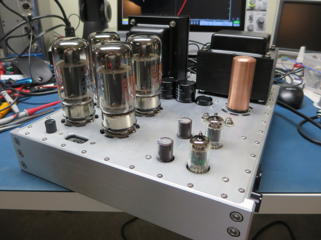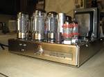
This truly is a beautiful build  There are a few things that came up though. Triode mode ?
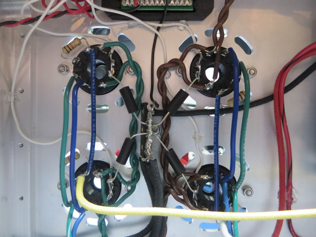
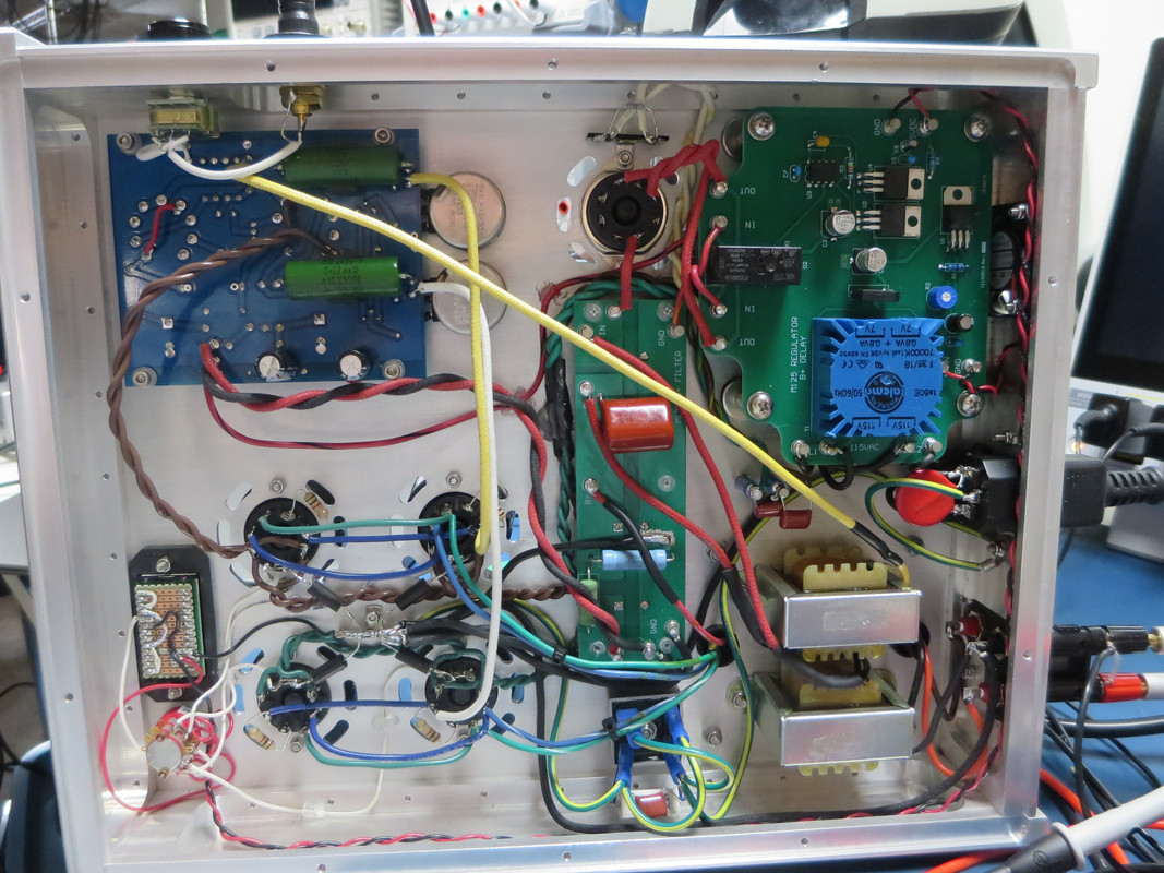
I guess that you did cut the groundplane traces on both sides of the input signal ground
connection, before connecting it again over the resistor on the pcb.
Or did you draw a dedicated wire from there to chassis ground that's not visible ?
There are two ground wires from the capasitor pcb to chassies ground right ?
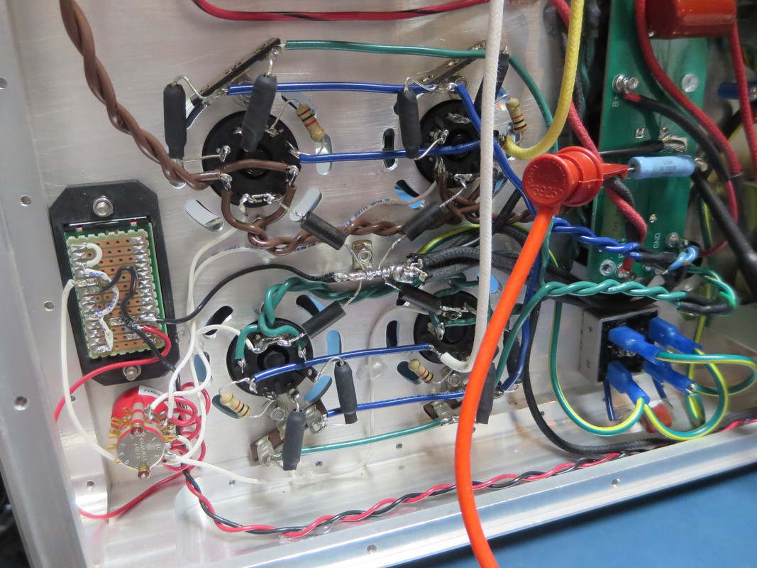
I guess that you are building/buying rectifiers in sockets. If building, "Cree" and "Infineon"
have some nice silicon carbide 1200v ones I'm using that I like.
Really a nice build and thanks again for the inspiration
Have you decided on what tubes to use ?
I guess that you did cut the groundplane traces on both sides of the input signal ground
connection, before connecting it again over the resistor on the pcb.
Or did you draw a dedicated wire from there to chassis ground that's not visible ?
There are two ground wires from the capasitor pcb to chassies ground right ?
I guess that you are building/buying rectifiers in sockets. If building, "Cree" and "Infineon"
have some nice silicon carbide 1200v ones I'm using that I like.
Really a nice build and thanks again for the inspiration
Have you decided on what tubes to use ?