
Good afternoon everyone. I hope all of you are having a good day and that all of you are safe.
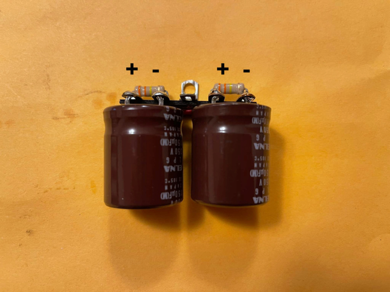
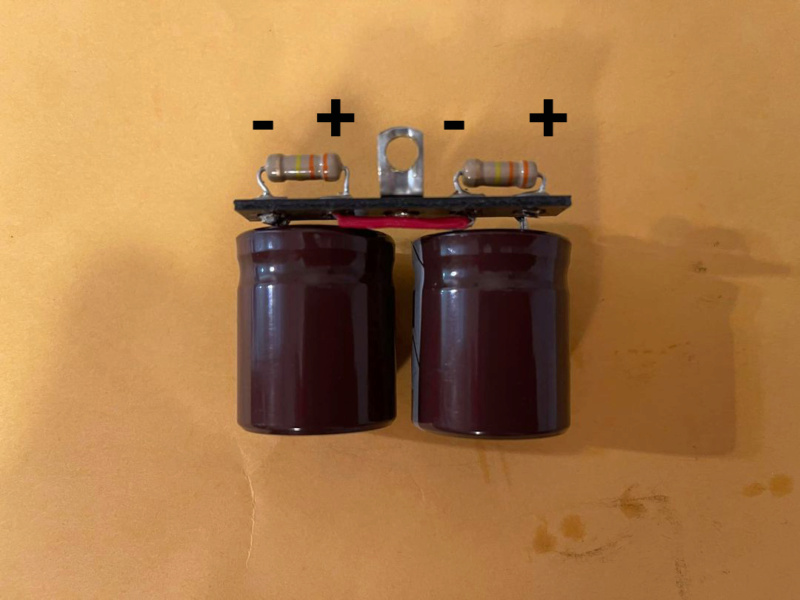
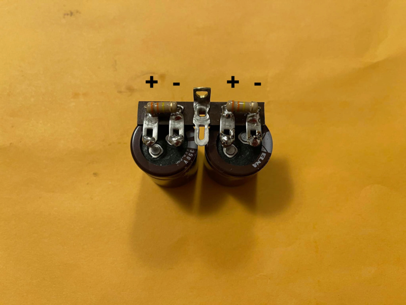
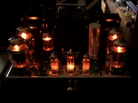
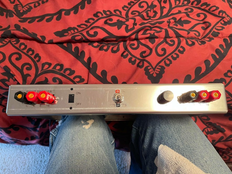
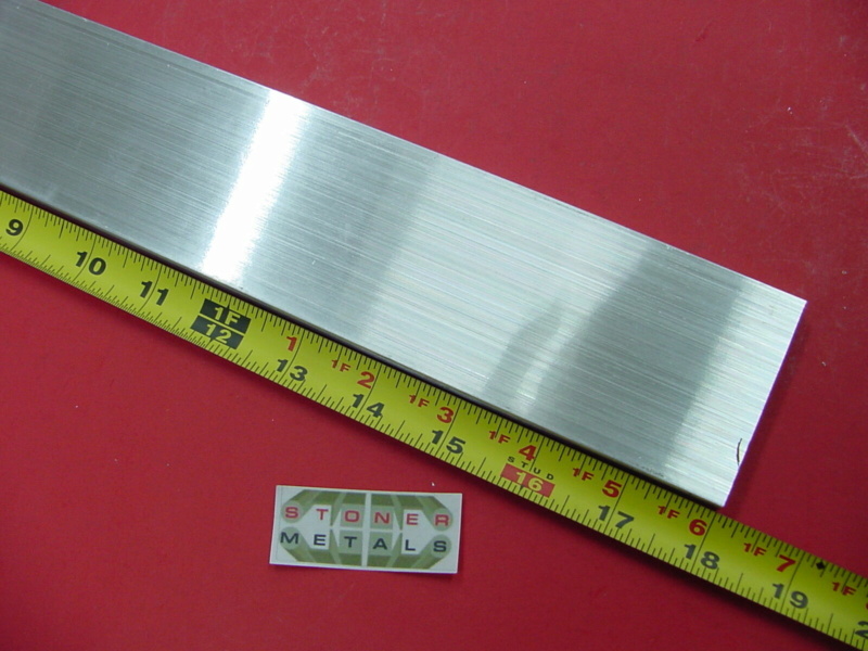
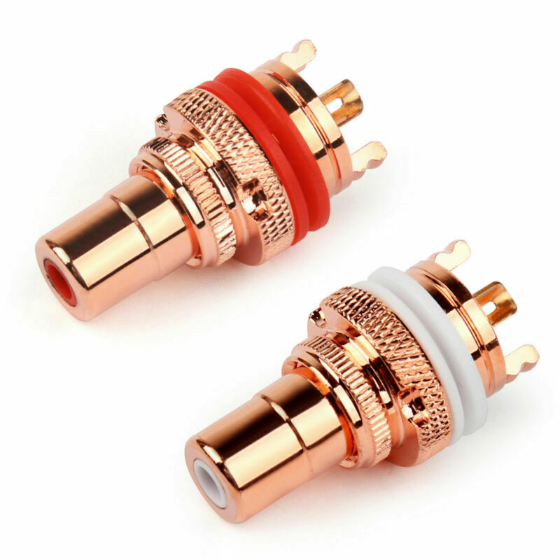
So far as you can see in the photos this is about as far as I can go with my assembly. I still have a lot of work to do on the chassis before I can start installing components. I also have a 3/8" x 2 1/2" x 18" aluminum flat bar stock on its way for the faceplate I’m going to install of the front of the chassis. I also have some copper RCA inputs to install on the back of the chassis.
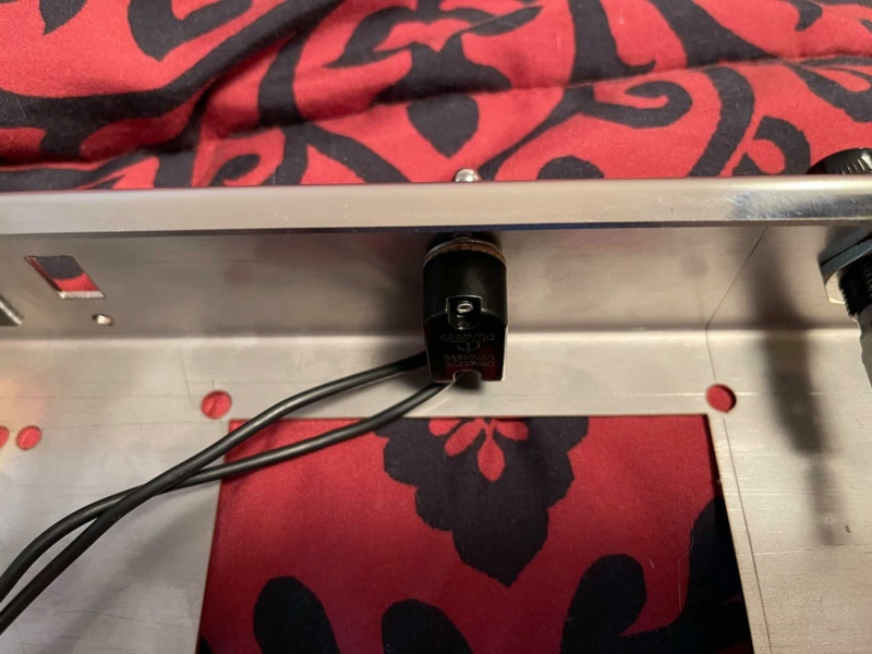
I need to get a machinist to cut the hole for the AC power entry module that I am going to install on the back of the chassis where the original power switch was to be installed.
I also need to drill two holes in the back on both sides of the new power switch location for the left and right RCA imputes. Then I plan on painting the chassis and the transformers.
I'm also going to install two 1v analog power meters in the front so I can visually see where the bias is set on the amplifier.
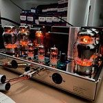
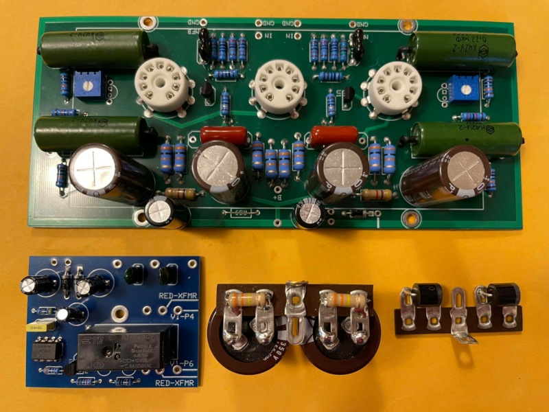
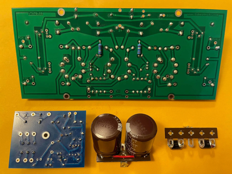
Also as most of you already know I am going to install the driver board on the outside of the amplifier up on some standoffs with a see-through Dynaco style cage where you can see the components but you can't touch them with your fingers. Plus I will have outlet holes for the driver tubes to stick out of the top of the driver cage.
All of you have a good day and clear skies and stay safe.
Tom
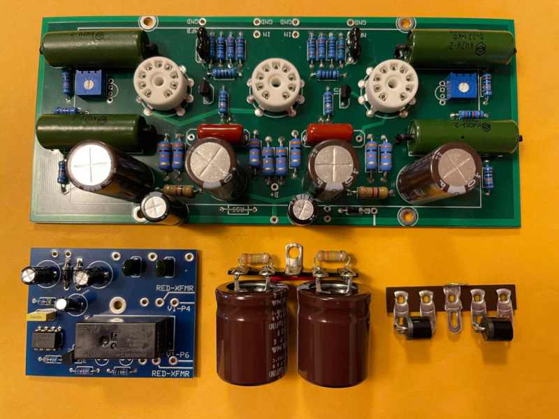

So far as you can see in the photos this is about as far as I can go with my assembly. I still have a lot of work to do on the chassis before I can start installing components. I also have a 3/8" x 2 1/2" x 18" aluminum flat bar stock on its way for the faceplate I’m going to install of the front of the chassis. I also have some copper RCA inputs to install on the back of the chassis.
I need to get a machinist to cut the hole for the AC power entry module that I am going to install on the back of the chassis where the original power switch was to be installed.
I also need to drill two holes in the back on both sides of the new power switch location for the left and right RCA imputes. Then I plan on painting the chassis and the transformers.
I'm also going to install two 1v analog power meters in the front so I can visually see where the bias is set on the amplifier.
Also as most of you already know I am going to install the driver board on the outside of the amplifier up on some standoffs with a see-through Dynaco style cage where you can see the components but you can't touch them with your fingers. Plus I will have outlet holes for the driver tubes to stick out of the top of the driver cage.
All of you have a good day and clear skies and stay safe.
Tom