The Dynaco Tube Audio Forum

Would you like to react to this message? Create an account in a few clicks or log in to continue.
The Dynaco Tube Audio Forum

Dedicated to the restoration and preservation of all original Dynaco tube audio equipment - Customer support for Tubes4hifi VTA tube amp and preamp kits and all Dynakitparts.com products


+14
jjones3318
peterh
skriefal
arledgsc
Sprags
ruffian
Luddite
Roy Mottram
Maintarget
baddog1946
Bob Latino
corndog71
ramon68
sKiZo
18 posters

    Custom Chassis?

    sKiZo
    sKiZo


    Posts : 1530
    Join date : 2013-04-01
    Location : Michigan USA

    Custom Chassis? - Page 3 Empty Re: Custom Chassis?

    Post by sKiZo Sun Jun 09, 2013 9:21 pm

    Ah, you remembered the part about me likee loud. tongue

    OK then ... enough is enough!!

    sKiZo
    sKiZo


    Posts : 1530
    Join date : 2013-04-01
    Location : Michigan USA

    Custom Chassis? - Page 3 Empty Re: Custom Chassis?

    Post by sKiZo Sat Jul 06, 2013 7:59 pm

    Been some progress here ... tried updating earlier, but couldn't find the thread.

    Got the case together and the iron mounted ...

    Custom Chassis? - Page 3 Assembly-iron

    Turned out pretty decent I think. I added some dense foam strips to the dadoes that trap the top plate in the sides, then just used pocket screws to draw it together. Right tight, vibration proof, and feels solid. I'm leaving the iron bare. Once I cleaned off all the stack glue and polished them up, they looked good. The bells took on a nice gray metal tone. A couple coats of Never Dull metal polish should keep them from rusting or changing color.

    I did have a dOH! moment on the back panel.

    Custom Chassis? - Page 3 Assembly-back-panel

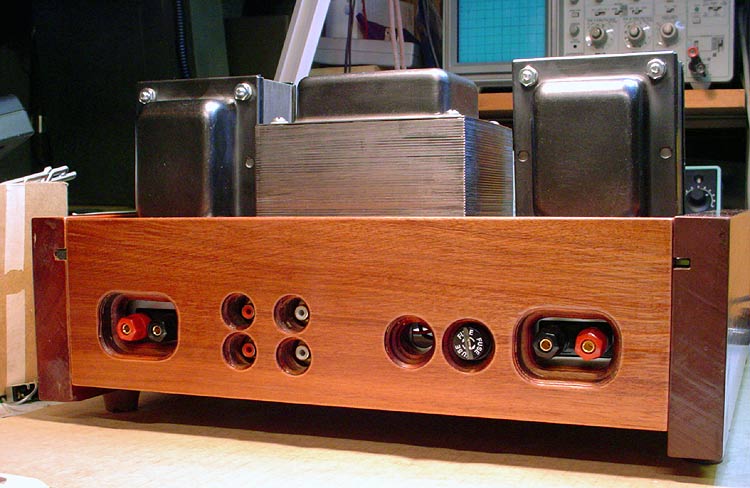
    I plan to use banana plugs with the speaker 5way jacks, and plenty of room for robust RCA interconnects. Couldn't get the fuse out though. dOH! Easy fix ... I just dremeled a slot into the cap - insert dime, twist, problem solved.

    Here's the internal layout. Amazing what a couple inches of height and depth can do. I kept looking about for stuff I forgot to put in. tongue 

    Custom Chassis? - Page 3 Assembly-internals

    I just cut straps for the caps out of roofing tin and used available mounting screws. Only thing missing is a small power converter I got coming to provide 24v for the light on the power switch. Pure bling there. The meters won't get mounted till the job's almost done to minimize movement shock. No sense bouncing them around any more than I have to.

    One concern ... the chokes are mounted to the wooden sides. Do they need to ground thru the mounting tabs? No big deal if I have to run a couple straps to the main chassis plate.

    All in all ... the hard part's done. Time to get out the soldering gun and see if I can blow it up!
    Bob Latino
    Bob Latino
    Admin


    Posts : 3265
    Join date : 2008-11-26
    Location : Massachusetts

    Custom Chassis? - Page 3 Empty Re: Custom Chassis?

    Post by Bob Latino Sat Jul 06, 2013 8:34 pm

    sKIZo,

     First of all you have done a great job with your custom VTA ST-120 ... This is only my opinion now - BUT - with all the wood work and custom chassis etc. I think you should paint the transformers. Some satin black paint would look nice with the black knobs, black tube sockets etc., etc. With that pale "gray look" you have now on the transformers, the transformers will look sort of "unfinished" when compared to the rest of the amp which looks beautiful.

    I have tried a lot of black paints on the transformers on these amps and my favorite now is the Krylon Fusion "Satin Black" which is Krylon's #2421 spray paint. This gives a low gloss subdued black color with a very durable surface.

    Bob
    sKiZo
    sKiZo


    Posts : 1530
    Join date : 2013-04-01
    Location : Michigan USA

    Custom Chassis? - Page 3 Empty Re: Custom Chassis?

    Post by sKiZo Sat Jul 06, 2013 9:14 pm

    Food for thought on the paint - but the pics really don't do the finish I got justice. I'm was figuring I'll get some interesting highlights by tube glow. Still ... I'll think on that for a while. Give me an excuse to enjoy the weather while I'm "thinking" ... a concern there would be how deep the Never Dull soaks in - I expect a good wipe with mineral spirits should clean that off for paint prep.

    So, no problem with the chokes? I don't believe the cases are part of the circuit, but I'd have to research that. Probably easier to just add the ground wires I mentioned earlier. I suppose that'd also tend to drain any other crap that hits the frame.

    I was also wondering about stretching the leads from the VTA board to the new bias pots. I was gonna go with some flat ribbon wire I got, but figure can't go wrong with twisted 22 gauge instead. That's a few inches more rf exposure to the leads, but I don't see that as an issue with those particular wires. Main concern for noise is the runs from the VTA board to the input jacks on the back. There's two sets, but they'll be bridged internally to eliminate external Y connectors, as I'll be feeding the amp from a tape loop on my quad receiver. I was thinking I'd add a metal shield behind those jacks also to minimize any noise potential.

    sKiZo
    sKiZo


    Posts : 1530
    Join date : 2013-04-01
    Location : Michigan USA

    Custom Chassis? - Page 3 Empty Re: Custom Chassis?

    Post by sKiZo Mon Jul 08, 2013 5:22 pm

    Bob Latino wrote:sKIZo,

    This is only my opinion now - BUT - with all the wood work and custom chassis etc. I think you should paint the transformers. Some satin black paint would look nice with the black knobs, black tube sockets etc., etc.

    You got me looking ... and if I look REAL close, I can already see a slight dusting of what looks suspiciously like rust. Sad 

    Good time to catch it as I haven't gotten into wiring it up yet. Have to pOp them puppies off and paint them. Sometimes it does pay to be slower than molasses in January.

    Thanx for making me look.

    EDIT >> Just got back from wandering thru the local hardware stores. Didna find the Krylon till the fourth stop. Dedication, eh ... tongue 

    Bit humid today, but also one of those merciless July blue skies ... great day for baking transformers!

    Custom Chassis? - Page 3 Xformer-bake-paint

    Do people rub these out, or just put a little wax on? I was also thinking of hitting the stacks with a 3M 00 pad to knock the shine off those for a two tone industrial look.

    BTW ... a shop turntable is wunnerful for this ... I hit the bottoms just to seal them, then flipped them over onto the wood boards. From there, I could move them back and forth to the turntable and then to the drying area. Worked pretty slick.
    Bob Latino
    Bob Latino
    Admin


    Posts : 3265
    Join date : 2008-11-26
    Location : Massachusetts

    Custom Chassis? - Page 3 Empty Re: Custom Chassis?

    Post by Bob Latino Tue Jul 09, 2013 8:15 pm

    Those transformers are looking good in satin black ... I get my Krylon Fusion #2421 at my local Wal-Mart. The other Wal-Mart a little further away from me also carries this Krylon #2421 paint.

    As to rubbing the transformers down to tone down the finish a little ... I guess that is up to you ... I wouldn't use steel wool on them ... even the fine 0000 ... You could try the rubbing compound if the surface seems too shiny for you. You might try spraying another metal surface and then trying the rubbing compound on that "trial" surface to see if you like the rubbed surface or not? The surface with #2421 isn't as shiny as glossy black which I don't like but others may like it ? Personally I like them as they are with the "satin" (low gloss) black finish ..

    One other thing .. After the painted transformers are mounted and you start to wire the amp, you should do something to protect that painted surface of the transformers as you wire the amp. Some builders make up some kind of wooden "jig" to hold the amp above the surface they are working on so the transformers don't actually touch the surface below. Other builders make sure that they have the transformers resting on a soft surface like an old towel or blanket so the nice black finish won't get marred ..

    Bob
    sKiZo
    sKiZo


    Posts : 1530
    Join date : 2013-04-01
    Location : Michigan USA

    Custom Chassis? - Page 3 Empty Re: Custom Chassis?

    Post by sKiZo Fri Jul 19, 2013 8:45 pm

    Transformer blanket ... check!

    ********

    Finally getting into the wiring ... funny ... it don't look anything like the pics included with the kit ...

    Custom Chassis? - Page 3 Wiring-stage-one

    It does get a bit busy in around here ...

    Custom Chassis? - Page 3 Wiring-v1-scm

    Came up short a couple mounting holes in the chassis. I ended up adding a bridge bracket for the SCM that uses one output xformer and one power xformer mount. I did something similar for the pentode/triode assembly. That also didn't have a handy location to mount the terminal strips, and the bracket is just fit under the switches.

    Custom Chassis? - Page 3 Pt-switch-bracket

    Wires will get dressed out a bit better once it's up and running ... still got a ways to go on that.
    avatar
    Sprags


    Posts : 123
    Join date : 2013-02-27

    Custom Chassis? - Page 3 Empty Re: Custom Chassis?

    Post by Sprags Sat Jul 20, 2013 1:45 am

    All this stuff looks really nice....if I ever have a house I can setup shop in I'd like to give this kind of stuff a try. Thanks for all the good info and beautiful photos.
    sKiZo
    sKiZo


    Posts : 1530
    Join date : 2013-04-01
    Location : Michigan USA

    Custom Chassis? - Page 3 Empty Re: Custom Chassis?

    Post by sKiZo Sat Jul 20, 2013 1:37 pm

    Home ownership is a big plus, but it doesn't take a lot of space to set up shop ... here's my 8x8 cubicle ...

    Custom Chassis? - Page 3 Workbench-002

    Custom Chassis? - Page 3 Workbench-003

    Granted ... a bit too cozy for a lot of folk, but ... everything is in easy reach!  Cool 

    Couple big pluses ... lots of light, and I'm blessed with a dry basement.

    PS ... thanx for the incentive to clean it up a bit for the pics ... usually gets a bit ragged this stage of a project. Had a lot of tools that I don't need anymore that got shuffled back to the garage ...

    And before anyone says anything. That IS clean ... you shoulda seen it before! tongue
    avatar
    Sprags


    Posts : 123
    Join date : 2013-02-27

    Custom Chassis? - Page 3 Empty Re: Custom Chassis?

    Post by Sprags Sat Jul 20, 2013 2:07 pm

    Any kind of a place to setup shop is nice. I do have a house in Charlotte, NC ..but I'm renting it out and cur renting a condo in Cincinnati. I have one car garage packed with boxes of items I don't have room for in the condo and my motorcycle...after all a 3 bedroom house with basement and 2 garage gave me enough room for everything. One day I hope to have my drill press, table saw and all my other tools out for easy access. I imagine working strictly on electronics doesn't require as big of a shop as if you work on cars, motorcycles or houses.
    avatar
    ramon68


    Posts : 118
    Join date : 2009-04-12
    Age : 83
    Location : naples fl

    Custom Chassis? - Page 3 Empty Re: Custom Chassis?

    Post by ramon68 Sun Jul 21, 2013 5:39 pm

    I was wondering how far astray this thread wound go. Anybody remember "Custom Chassis?"
    Bob Latino
    Bob Latino
    Admin


    Posts : 3265
    Join date : 2008-11-26
    Location : Massachusetts

    Custom Chassis? - Page 3 Empty Re: Custom Chassis?

    Post by Bob Latino Sun Jul 21, 2013 6:04 pm

    Ramon is correct ... Look ... I deleted those posts on the "weather in wherever?" on this thread ...  Please stick to posts that coincide with what the original poster posted on this thread which was > A custom chassis for the VTA ST-120 amp ...

    Bob
    avatar
    Sprags


    Posts : 123
    Join date : 2013-02-27

    Custom Chassis? - Page 3 Empty Re: Custom Chassis?

    Post by Sprags Sun Jul 21, 2013 6:28 pm

    Yeah...sorry for my part....anyway...nice job on the build.
    sKiZo
    sKiZo


    Posts : 1530
    Join date : 2013-04-01
    Location : Michigan USA

    Custom Chassis? - Page 3 Empty Re: Custom Chassis?

    Post by sKiZo Wed Jul 31, 2013 6:39 pm

    Weather update ... it's raining here ... lol! 

    Which got me down in the shop for phase two of the wiring. Output transformers are wired and also built the TP network ... Farther along I get, the less it looks like the pics provided with the kit. Thanks Bob for the detailed point to point instructions.

    Custom Chassis? - Page 3 Wiring-session2

    Here's a closeup of the network.

    Custom Chassis? - Page 3 Tp-wired

    PS ... nice job on the TP insert that supplements the point to point instructions. I started out using the manual and found it easier to just follow the pin assignments on the diagram ...

    Enough for today ... take my time and I might even get it right, right? So far I haven't noticed any horrible mistakes, but that usually happens first time you apply juice anyway.
    sKiZo
    sKiZo


    Posts : 1530
    Join date : 2013-04-01
    Location : Michigan USA

    Custom Chassis? - Page 3 Empty Re: Custom Chassis?

    Post by sKiZo Mon Aug 05, 2013 2:34 pm

    Just to verify ... the circled connections are supposed to be bridged when soldered? Looks like the bridges and filament connections are at pin 1 (primary plate) and pins 5-6 (heater and plate 1) ...

    EDIT > Roy says I can't count. He's right. Those are pins 4&5 and pin 9 (not pin 1) for the filaments

    Custom Chassis? - Page 3 Mini9-bridges

    Bit of a head scratcher as ...

    - the detail drawing in the VTA assembly instructions shows white space between the dots for the FIL connections
    - It's kinda hard to tell from the bottom that there's bridge traces between the connections once the board's soldered
    - I obviously didn't pay close enough attention when first getting into it
    - And the lack of a true schematic makes it a bit hard to trace the logic

    Seems fairly obvious from the photo I found at the website that they should be bridged, but just wishing to confirm before checking that off my list of possible fu ... fu ... fundamental misteaks. tongue


    Last edited by sKiZo on Fri Aug 09, 2013 12:02 am; edited 1 time in total
    sKiZo
    sKiZo


    Posts : 1530
    Join date : 2013-04-01
    Location : Michigan USA

    Custom Chassis? - Page 3 Empty Re: Custom Chassis?

    Post by sKiZo Mon Aug 05, 2013 2:55 pm

    Another fiddlybit ... there's four sets of TWO pin six connections on the VTA board, but only ONE required per tube?

    The pics provided show only one connection at each set ... mostly wondering what the other hole is for. Legacy?
    Bob Latino
    Bob Latino
    Admin


    Posts : 3265
    Join date : 2008-11-26
    Location : Massachusetts

    Custom Chassis? - Page 3 Empty Re: Custom Chassis?

    Post by Bob Latino Mon Aug 05, 2013 3:28 pm

    sKiZo,

     Yes - Those connections are already bridged on the board - they are the filament connections for the three driver tubes.

    "Another fiddlybit ... there's four sets of TWO pin six connections on the VTA board, but only ONE required per tube?"

    These are marked as PIN 6 eyelets on the bottom of the driver board not TWO pin 6 as you mentioned. They used to say "To pin 6" they never said "TWO pin 6"

    On the latest version of the driver board Roy left off the "To" from the "PIN 6". The newer driver board just say "PIN 6". Yes there is one "PIN 6" eyelet for each output tube. Run a wire from each of the four PIN 6 eyelets to pin 6 of each output tube.

    Bob
    sKiZo
    sKiZo


    Posts : 1530
    Join date : 2013-04-01
    Location : Michigan USA

    Custom Chassis? - Page 3 Empty Re: Custom Chassis?

    Post by sKiZo Mon Aug 05, 2013 4:29 pm

    Thanx for the quick response.

    Those connections are already bridged on the board - they are the filament connections for the three driver tubes.

    As I expected, but appreciate the confirmation. I dressed the socket pins when I put it together and it was kinda hard to tell. Maybe next time you print up the VTA assembly instructions, you could take a look at that drawing and add the bridges? That's what had me wondering.

    Yes there is one "PIN 6" eyelet for each output tube. Run a wire from each of the four PIN 6 eyelets to pin 6 of each output tube.

    Sorry bout the confusion, but looking at the board in the posted, there are TWO "PIN 6" eyelets at each location. Actually, there's only one marked "PIN6" at each location and the other hole right near it is unmarked. Like I say, it looks like that's either a legacy pin that's no longer used, or there's plans for something else down the road? Maybe planning for the octal board? Either way, I'll do one connection to each pin 6 and just leave the other hole alone.

    So ... that leaves me with basically the front panel, input wiring, and installing the plug. I ordered some Mogami W2947 shielded wire mentioned in another thread ... it's shipped, but looks like I get a couple days off.

    Here's what it looks like as we speak ...

    Custom Chassis? - Page 3 Wiring-session3-full

    Still waiting for it to start looking like an ST-120 ... guess I should stop holding my breath ... clown
    Bob Latino
    Bob Latino
    Admin


    Posts : 3265
    Join date : 2008-11-26
    Location : Massachusetts

    Custom Chassis? - Page 3 Empty Re: Custom Chassis?

    Post by Bob Latino Mon Aug 05, 2013 5:24 pm

    "Sorry bout the confusion, but looking at the board in the posted, there are TWO "PIN 6" eyelets at each location. Actually, there's only one marked "PIN6" at each location and the other hole right near it is unmarked. Like I say, it looks like that's either a legacy pin that's no longer used, or there's plans for something else down the road? Maybe planning for the octal board? Either way, I'll do one connection to each pin 6 and just leave the other hole alone"

    The other hole that is connected on the board to that "PIN 6" hole is a hole (which should be) for the outer eyelet for each Russian PIO cap. If that hole is empty then you didn't use the outermost connection for each Russian PIO cap. In the VTA ST-120 driver board manual it tells you to spread the leads of each Russian PIO cap until there is a 1 9/16ths inch distance between the two leads. If you do that then the two leads on each Russian PIO cap will drop into the two outer holes for the cap and that hole will be filled.

    Bob
    sKiZo
    sKiZo


    Posts : 1530
    Join date : 2013-04-01
    Location : Michigan USA

    Custom Chassis? - Page 3 Empty Re: Custom Chassis?

    Post by sKiZo Mon Aug 05, 2013 5:59 pm

    Aha ... I sit corrected! The inner hole for the standard filter caps worked fine, if a bit tight. Mayhaps I have a bit more flexibility with my layout than there'd be with a standard build ... helps that I insulated the outer cases of the PIO's so I don't have to worry about the center conductor shorting there ...

    Also looks like the "PIN 6" hole is bridged to both the inner and outer filter cap holes, so either hole would work. I just used the one that was easier to get to at each connection.

    WONDERING OUT LOUD

    I have a variac ... would it be a good idea to bring it up on that first, or just plug it in and follow the initial startup instructions? I do plan to do a dim bulb test first go round ...
    Bob Latino
    Bob Latino
    Admin


    Posts : 3265
    Join date : 2008-11-26
    Location : Massachusetts

    Custom Chassis? - Page 3 Empty Re: Custom Chassis?

    Post by Bob Latino Mon Aug 05, 2013 6:50 pm

    Just follow the start up procedure as outlined in the assembly manual. You don't really need a variac ..

    The key step is the SECOND step when you power up one channel WITH THE RECTIFIER in there. With the rectifier, you now have high voltage in the amp (about 500 VDC in the VTA ST-120) This is the step that causes a problem with a few builders who don't have the high voltage storage system wired correctly OR have a bad solder joint somewhere OR have two connections touching that should not be touching.

    If you pass step ONE in the startup procedure, then you have the power transformer wired correctly.
    If you pass step TWO and that channel biases up correctly, then the high voltage system is OK and you can now power up both channels (step 3)

    Bob
    sKiZo
    sKiZo


    Posts : 1530
    Join date : 2013-04-01
    Location : Michigan USA

    Custom Chassis? - Page 3 Empty Re: Custom Chassis?

    Post by sKiZo Mon Aug 05, 2013 8:35 pm

    And let me guess ... step three is running for the fire extinguisher! affraid 

    One other mod I'm still pondering is a 24v power supply for the panel lights. Problem being, the board doesn't fit where I expected it to. Was gonna just mount it to the side, but there's a lot of wiring in the way now.

    So, the infamous PLAN B!

    Custom Chassis? - Page 3 24v-ps-testfit

    The bracket is sturdy enough, and I believe it'll also help shield the input jacks a bit from the transformer itself. Bolt it down in the back and just press a couple blobs of windshield sealant caulk between the transformer and plate. If it'll hold a windshield in a car at 100mph+, I don't figure it'll let go in this application. That should help damp it if there's any potential vibration issues. Don't expect any, but ... some nylon bolts should hold the board to the bracket nicely.

    Unless ... is there any place on the chassis where I can tap 24v DC (or thereabouts) for the lights?
    sKiZo
    sKiZo


    Posts : 1530
    Join date : 2013-04-01
    Location : Michigan USA

    Custom Chassis? - Page 3 Empty Re: Custom Chassis?

    Post by sKiZo Thu Aug 08, 2013 5:23 pm

    Having second thoughts about jumping the inputs to two sets of jacks ...

    For one, I can always go with an external Y cable or hard adapter ...

    For another, I'd be interested in maybe going with dedicated L+R and L-R jacks. L+R should give me a center channel to punch the vocals, and L-R is usually a good feed if you want to add a sub.

    ?

    Too late to add a couple more jacks to the box. More work than it's worth, so that ship has sailed.
    Roy Mottram
    Roy Mottram
    Admin


    Posts : 1839
    Join date : 2008-11-30

    Custom Chassis? - Page 3 Empty Re: Custom Chassis?

    Post by Roy Mottram Thu Aug 08, 2013 8:41 pm

    way back to post#65, those are pins 4&5 and pin 9 (not pin 1) for the filaments
    sKiZo
    sKiZo


    Posts : 1530
    Join date : 2013-04-01
    Location : Michigan USA

    Custom Chassis? - Page 3 Empty Re: Custom Chassis?

    Post by sKiZo Fri Aug 09, 2013 12:05 am


    dOH! jocolor 

    Corrected the post.


    Sponsored content


    Custom Chassis? - Page 3 Empty Re: Custom Chassis?

    Post by Sponsored content


      Current date/time is Sun Jun 30, 2024 1:51 am