The Dynaco Tube Audio Forum

Would you like to react to this message? Create an account in a few clicks or log in to continue.
The Dynaco Tube Audio Forum

Dedicated to the restoration and preservation of all original Dynaco tube audio equipment - Customer support for Tubes4hifi VTA tube amp and preamp kits and all Dynakitparts.com products


+14
jjones3318
peterh
skriefal
arledgsc
Sprags
ruffian
Luddite
Roy Mottram
Maintarget
baddog1946
Bob Latino
corndog71
ramon68
sKiZo
18 posters

    Custom Chassis?

    sKiZo
    sKiZo


    Posts : 1530
    Join date : 2013-04-01
    Location : Michigan USA

    Custom Chassis? - Page 4 Empty Re: Custom Chassis?

    Post by sKiZo Mon Oct 07, 2013 8:31 pm

    Rainy days and Mondays,
    Always get me down ...


    (in the workshop) Cool 

    And ... ladies and germs, for your edification and pleasure tonite ... I bring you ...
    (drumroll please)

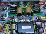
    The obligatory first glow shot ...

    Custom Chassis? - Page 4 First-power-up-002

    That's my "backup" set - a Chinese rectifier, RCA clear tops, and a set of Psvane HiFi KT88's. I figure to hold off a bit on the KT120's, my special set of drivers, and a high end rectifier until I'm sure the amp is right.

    Everything biased stable at 55mv, and got sound. Left it running full power into dummy loads for about an hour and transformers weren't heating at all. Wahoo!

    Couple fiddlybits to take care of ...
    - I got the volume pots bass ackwards. Simple wire swap end to end should take care of that.
    - Ditto on the bias pots on the right bank. Same fix.

    The panel meters are WAY off ... with 55mv on two different VOMs, those are showing 70. Have to dig into those and see what I got for adjustment. No biggie - even if I can't get them adjusted properly, they're consistent, so I can just remember the error level. Still glad I also included the test taps. Oh, yeah ... two of the test taps are mighty tight, so I'll ream those out a bit when I dig into the rest.

    I do have an issue with the input wiring. Had a helluva hummmm in the left channel when I first powered up. Played around with the easy stuff first, and found that I could get good sound out of both channels by holding the center pin of the RCA cable to the outer jacket of the socket. So, once again ... should be a simple wire swap. I expect the reversed wiring on the volume pots have something to do with it. Good news is there's no hum and I get a clean signal when I fudge the connectors, so the long runs to the back of the box should work fine.

    Having taken some ... er ... uh ... "liberties" with the original design, I'm surprised that's all that's wrong. My biggest concern was the PT network, but both sides are working, and I do get the expected watt drop in triode mode.

    PS ... even when I figured out the input issue, the left channel was still tinny. Huh? Come to find out the el cheepo speaker I got tacked up into the rafters had fallen out of the case. dOH! A bit of duck tape took care of that. Would all life's problems be so simple.

    Done for now ... I'll dig in tomorrow and take care of the short list. Can't wait to see what it sounds like on REAL speakers ...
    Maintarget
    Maintarget


    Posts : 227
    Join date : 2013-02-10

    Custom Chassis? - Page 4 Empty Re: Custom Chassis?

    Post by Maintarget Mon Oct 07, 2013 9:36 pm

    Looking good cant wait for more photos:cyclops: 
    arledgsc
    arledgsc


    Posts : 502
    Join date : 2012-11-30

    Custom Chassis? - Page 4 Empty Re: Custom Chassis?

    Post by arledgsc Tue Oct 08, 2013 10:03 am

    Congrats!  Long time coming and glad to see you are near the end...
    sKiZo
    sKiZo


    Posts : 1530
    Join date : 2013-04-01
    Location : Michigan USA

    Custom Chassis? - Page 4 Empty Re: Custom Chassis?

    Post by sKiZo Tue Oct 08, 2013 1:58 pm

    glad to see you are near the end...

    wOw ... taken out of context, that could be disheartening. tongue 

    But ... as you say ...

    Just spent about an hour cleaning up the issues I had on first start. Reversed the pots (no more up for down, and vice versa) and the input jack issue was due to a couple reversed wires on the common ground - as expected. Also gave it another good shake 'n blow to make sure I got rid of all the construction debris ... I still plan to do one last sweep thru all the connections with my magnifying glass and mini-sledge to make sure everythings tight 'n right.

    I also moved the CL90 thermister to the right leg of the AC power. Had that on the return line ... dOH!

    Great sound on the toy speakers I got in the workshop, and absolutely quiet when I kill the CD ... I did blow a fuse on the variac (not on this project) and spaced it, so I got a good excuse to get out on the bike and roll out to the RatShack for some spares. Once I get that fired up, should be interesting to see what I get for voltage at the test points with that inline and just direct from the wall.

    Still gotta make a cover for the bottom, but that should be simple enough. Once that's done, drag it upstairs and put it to use.

    Real close now ... thanx everybody for coming along for the ride ... are we there yet? Are we there yet?? cheers
    sKiZo
    sKiZo


    Posts : 1530
    Join date : 2013-04-01
    Location : Michigan USA

    Custom Chassis? - Page 4 Empty Re: Custom Chassis?

    Post by sKiZo Tue Oct 08, 2013 10:32 pm

    OK then. Got the variac working and as expected, the test voltages dropped down into range when I set that to 118vac. Hauled the beast up out of the basement, hooked it up, and after some fiddling with the system hookups, got it working.

    I really really think I'm gonna like this thing!

    Not really noticing any difference in power going from 200wpc on the McIntosh to 70wpc with the ST120. Some kinda magic going on there ... apparently tube watts ARE bigger than solid state watts. Just playing around a bit with some mixed material, and real happy with the results. Glad I added the volume controls, as that allows me to adjust the amp to the input and get a good match with the rest of the equipment. Driving it off a tape loop on my Sansui quad, and YES ... my internal "Y" adapter seems to be doing the trick. Like belly buttons ... think of this one as an "innie" ... tongue 

    Can't A/B compare with the MC2205 amp yet, but it seems to be doing at least as well on the soundstage, and the dynamics are incredible. This amp actually seems to be a better match to the speakers than the MC2205 - no more flashing lights on the speaker guard circuits like I'd get with the Big Mac. Bass was a bit down, but nothing I couldn't fix with a bit of EQ, and a couple tweaks give me impact without the boom, just the way I like it. I'm thinking this one's a keeper ...

    Some artsy fartsy with the camera ... Ignore the meter readings - those are way off. I tracked 55ma all the way thru the circuit right up to the back of each meter, so for now I'm just going with a VOM using the standard bias jacks.

    Custom Chassis? - Page 4 Installed-006

    Custom Chassis? - Page 4 Installed-008

    Custom Chassis? - Page 4 Installed-010

    May I has a dancing banana?

    Custom Chassis? - Page 4 20070331221204!Dancing_Banana
    Bob Latino
    Bob Latino
    Admin


    Posts : 3265
    Join date : 2008-11-26
    Location : Massachusetts

    Custom Chassis? - Page 4 Empty Re: Custom Chassis?

    Post by Bob Latino Tue Oct 08, 2013 11:23 pm

    sKiZo,

     Nice work on the amp .. Undoubtedly one of the best custom VTA ST-120's I have seen. You can easily see a lot of time and effort went into your build.

    Bob
    skriefal
    skriefal


    Posts : 135
    Join date : 2011-09-20
    Location : Utah, USA

    Custom Chassis? - Page 4 Empty Re: Custom Chassis?

    Post by skriefal Wed Oct 09, 2013 12:33 am

    sKiZo wrote:
    May I has a dancing banana?
    Here 'ya go:

    Custom Chassis? - Page 4 Peanut_Butter_Jelly_Time
    sKiZo
    sKiZo


    Posts : 1530
    Join date : 2013-04-01
    Location : Michigan USA

    Custom Chassis? - Page 4 Empty Re: Custom Chassis?

    Post by sKiZo Wed Oct 09, 2013 12:52 am

    Hardest part really was the design. Easy part was the electronics due to the concise and complete instructions, complete with forum and email support when I had any questions. And I thank you all for that.

    I just got done sitting thru a marathon session - couple hours of clicking thru the library, trying out some of the tried and true favorites. Old meets new and all that ... feeding a tuber with my state of the art digital HTPC. The amp handled everything I threw at it with grace and style. Last piece on the playlist was Blood, Sweat, and Tears, Blues - Part Two. That will work ANY system ...

    Truth be told, it sounds even better than it looks, and that's with the "second tier" tubes. I'll get used to those for a while and prepare to be even more pleasantly surprised when I start swapping in the good stuff. Not that the current combination is crap ... those clear tops are doing an outstanding job paired with the Psvane KT88's. I think tomorrow I'll swap in the WZ68 see what happens, but leave the rest alone for now.

    Did a bit of fine tuning while listening and the bass is figured out. Good and strong now, full with killer impact and no sign of clips or mud. Mostly just balancing the line levels thru the system. Digital out from the computer is at 93%, DAC is down three clicks, and the amp is at around one o'clock both sides. In case anyone's taking notes. tongue 

    One very pleasant report ... after a couple hours, absolutely no listening fatigue ... same playlist would have had me pretty much in a coma on the solid state amp. And the house is filled with that new amp smell! The amp is also dead quiet ... I paused the system and could barely hear a bit of hiss out of the speakers with my ear right up to them. Pure dumb luck there, but hey ... I'll take it.

    Once again, thanx for a great amp ... this here's a keeper!


    sKiZo
    sKiZo


    Posts : 1530
    Join date : 2013-04-01
    Location : Michigan USA

    Custom Chassis? - Page 4 Empty Re: Custom Chassis?

    Post by sKiZo Wed Oct 09, 2013 12:57 am

    skriefal wrote:
    sKiZo wrote:
    May I has a dancing banana?
    Here 'ya go:

    Custom Chassis? - Page 4 Peanut_Butter_Jelly_Time
    Right back atcha ...

    Custom Chassis? - Page 4 Giphy
    arledgsc
    arledgsc


    Posts : 502
    Join date : 2012-11-30

    Custom Chassis? - Page 4 Empty Re: Custom Chassis?

    Post by arledgsc Wed Oct 09, 2013 8:46 am

    those clear tops are doing an outstanding job paired with the Psvane KT88's
     I'm using Psvane KT-88s and they take a couple of hundred hours to break in.  So if you think it sounds good now wait a few months!  A lot more bass and clearer trebles...
    sKiZo
    sKiZo


    Posts : 1530
    Join date : 2013-04-01
    Location : Michigan USA

    Custom Chassis? - Page 4 Empty Re: Custom Chassis?

    Post by sKiZo Wed Oct 09, 2013 5:19 pm

    arledgsc wrote:
    those clear tops are doing an outstanding job paired with the Psvane KT88's
     I'm using Psvane KT-88s and they take a couple of hundred hours to break in.  So if you think it sounds good now wait a few months!  A lot more bass and clearer trebles...
    Got these HiFi's used ... supposed to have around 100 hours on them ...

    (Thanx Scott ... they're working fine!)

    By your estimate on break in, they're halfway there. Then again, I'm already getting antsy about getting those KT120's plugged in ... Must ... resist ...

    PS ... friend of mine just stopped by for a visit ... parked him in the comfy chair and had some serious trouble prying him out later ... much later. Next project may be an ejector seat ... Razz

    PPS ... I thought RCA clear tops were supposed to be flashers? Also, couldn't stand the suspense ... I just swapped in a Telefunken center with Gulbransen Bugle Boys on the sides ... those all need breaking in, so might as well get to it, right? I'll surprise myself with them later tonight.

    baddog1946
    baddog1946


    Posts : 319
    Join date : 2010-02-03
    Location : Costa Rica

    Custom Chassis? - Page 4 Empty Re: Custom Chassis?

    Post by baddog1946 Thu Oct 10, 2013 8:34 am

    Hey Skizo:
    Nice job on that. I enjoyed the running commentary as you evolved your deisign on this forum and did a superb job on the finishing.
    Your design has a unified look to it that shows a lot of thought and some good workmanship in both wood and metal. Any chance we can look under the hood?
    Baddog
    sKiZo
    sKiZo


    Posts : 1530
    Join date : 2013-04-01
    Location : Michigan USA

    Custom Chassis? - Page 4 Empty Re: Custom Chassis?

    Post by sKiZo Thu Oct 10, 2013 1:10 pm

    Sure ... stop on over! We're only talking a couple thousand miles ... shall I put the coffee on? I've got some good Jamaican too ... Smile 

    For me, the running commentary did a nice job of keeping on track and getting it right. Would have probably painted myself into a corner a time or two without being able to bounce ideas around here. Heck ... just seeing my thoughts in the posts allowed me to figure, "hey ... that can work" ... or "well, that's just silly" ...

    Most of these are reposts, but, hey  ... no shortage of pixels. Here's the final look.

    Custom Chassis? - Page 4 Wiring-last-stage

    I should still get under there and tweak the wires a bit, add some zip ties here and there ... maybe go old school and do a string wrap on the harness. I figured to hold off on that until I'm real sure there's no "issues" that need to be addressed, but right now, after the initial set of dOH!s were fixed, it seems to be working well.

    One advantage of solid core wire is it does tend to stay where you put it. The chassis does have sort of an "organic" look to it ... should I add another layer of square corner wires so it looks more like it's supposed to? geek 

    One other change that may have some people scratching their heads - with all the talk about input wiring options, I decided to just go with the twisted pairs, and routed those high and as far away from the possible interference points as I could. So far, it's working ... the amp is dead quiet on standby. That was a magic moment when I first lit it up. I may still foil wrap those along the side of the case for extra rejection, add a drain line to ground to the bundle, or maybe even add bypass caps on the jacks, or all of the above ... but right now, don't really see the need.

    ~~~

    And for a trip down memory lane ...

    Custom Chassis? - Page 4 Dry-fit-bottom-002

    Doesn't bear much resemblance to the final build, does it?

    ~~~

    This was probably one of the trickiest parts of the case.

    Custom Chassis? - Page 4 Pocket-screws

    There's six pocket screws that hold the whole thing together. The top panel is just trapped in dadoes around the perimeter. Added a bit of foam tape in the grooves for a tight yet flexible fit. Worked out real solid.

    ~~~

    This was my favorite part ... the T/P network ...

    Custom Chassis? - Page 4 Tp-wired

    Well now ... that doesn't look ANYTHING like it's supposed to!! affraid
    sKiZo
    sKiZo


    Posts : 1530
    Join date : 2013-04-01
    Location : Michigan USA

    Custom Chassis? - Page 4 Empty Re: Custom Chassis?

    Post by sKiZo Thu Oct 10, 2013 1:59 pm

    PROBLEM

    I piggybacked the meters onto the bias test points, assUming they had internal shunts.

    Setting the bias using a VOM at the test points to 55ma showed around 70ma on the meters, and I wrote it off as meter error.

    OOps ...

    Seems I had it bass ackwards. The meters were right, the test points were wrong.

    Hauled the beast back down to the bench and disconnected the meter leads, Without changing the pots, I now read around 70ma using a VOM at the bias test points. dOH!

    Seems I was cooking the tubes a bit high. Not enough to do any serious damage apparently, but enough to probably lose a few hours of life. Ah well ... glad I decided to check.

    SOLUTION

    Courtesy of one of the other boards ...

    - Snip the 10 ohm resistor off pin 8. Connect that to the + bias test jack for that socket.
    - Connect the meter + lead to pin 8
    - Connect the meter - lead to the + bias test jack

    Works perfectly. I set the bias to 55ma with the meters disconnected and prior to any mods. Did the mods, and without adjusting the bias pots, I'm now getting 55ma at both the test jacks and meter. Wahoo!

    One other minor tweak was with the circuit mods, I now have to isolate the connections to the ground side of the meters. Had a couple SPDT switches to select front or rear tube on each bank - replaced those with DPDT's.

    I'll also took this opportunity to replace one of the bias test jacks ... too tight to fit the VOM lead properly. Good idea to order extras (I did) and even better idea to make sure they work prior to installation.

    One new issue ... when I flip the meter switches to select the front or back tubes, I get a mild spike thru the speakers ... All RatShack had in mini DPDT's were center off ... think that's the problem?

    PS ... now that I've got the meter circuit figured out and working, the Velleman meters I'm using are surprisingly accurate and easy to read. I was just eyeballing the settings then checking the VOM, and getting very close ... close enough for an ex-government worker ...
    sKiZo
    sKiZo


    Posts : 1530
    Join date : 2013-04-01
    Location : Michigan USA

    Custom Chassis? - Page 4 Empty Re: Custom Chassis?

    Post by sKiZo Fri Oct 11, 2013 11:51 pm

    Well ... harumph.

    Now that the meters are working, and matching the VOM at the test points, the dang thing's clipping at the same levels I was using before the "fix" ...

    Something I'm missing here ...

    Question ... is it normal for the VOM to be swinging under load? I set the bias at 55ma with no input, and I'm seeing swings up to around 100ma peaks on both the meters and VOM when pushing it some. Can't say as I noticed that before modifying the meter circuit.
    baddog1946
    baddog1946


    Posts : 319
    Join date : 2010-02-03
    Location : Costa Rica

    Custom Chassis? - Page 4 Empty Re: Custom Chassis?

    Post by baddog1946 Sat Oct 12, 2013 10:39 am

    Skizo:
    Looks just as good under the hood as above board. Congrats!
    Which bias pots did you buy? How easily do they to adjust? I find the small board mounted pots are a little tweaky and too sensitive sometimes. I would like to find some pots with a slower taper.
    I designed a small board for the stock pots with the meter on it as well. It mounts on the front plate with everything close by for easy viewing it should be easy to get it right.  
    My project is still coming along slowly as people keep asking me to build them amps and I can't say no. (I am on my 5th ST70/120). I gotta do an M-125 one of these days.
    I have finally collected all the parts and brought them to the jungle for the final assembly. Watch out for the 160 amp Dynaco inspired 800DCV monster coming soon to a forum near you.
    You pointed out a few things and generated a lot of dialogue with your project that proved useful and educational. What have you got on your project list next?
    Baddog
    sKiZo
    sKiZo


    Posts : 1530
    Join date : 2013-04-01
    Location : Michigan USA

    Custom Chassis? - Page 4 Empty Re: Custom Chassis?

    Post by sKiZo Sat Oct 12, 2013 11:42 am

    My next project will be listening to this one ... once I work out the remaining bugs. Appreciate the congrats, but the fat lady isn't singing quite right yet. Plenty of opportunities left to blow it up!

    Still having issues with the meter circuit. Current plan is to haul it down to the shop one more time and strip the meter circuit entirely and go back to the stock bias hookup. If nothing else, that will eliminate that as the cause of the clipping. I'll also do a close up mark one eyeball exam to see if I might have fubared something else while I was in there.

    Sounds like you're the guy I need to be talking to on this meter circuit. I seem to be going in circles a bit. One thing I've noticed with the current mods - I'm getting some serious bounce under load ... Set the bias to 55ma with no signal, and I'm seeing excursions up to 100ma under heavy load ... this normal? It's on both the VOM and panel meters. Seems to me I should only be seeing small fluctuations no matter what I'm throwing at it.

    Pots ... I paid top dollar for mine ... Buck a piece on that auction site. 

    http://www.ebay.com/itm/6-Pack-Potentiometer-B50k-16mm-Base-Dia-20mm-Shaft-/271160227085?ssPageName=ADME:L:OC:US:3160

    ************

    EDIT > > Already broke one of the Chinese pots. One went open, so I went ahead and ordered some OEM Fender 50k Linears to replace them all.

    http://www.tubesandmore.com/products/R-V50KA-SP-EC

    Twice the size, so I'll have to retap the holes, but plenty of room. Also roller type, so they should be durable.


    ************


    Last edited by sKiZo on Mon Nov 11, 2013 3:54 pm; edited 1 time in total
    baddog1946
    baddog1946


    Posts : 319
    Join date : 2010-02-03
    Location : Costa Rica

    Custom Chassis? - Page 4 Empty Re: Custom Chassis?

    Post by baddog1946 Sat Oct 12, 2013 1:48 pm

    skizo;
    You mentioned something that I caught in your last entry.  You said 55ma. referring to the readings. There are two ways to wire a bias circuit: parallel or series one is ma. and the other is mv.
    Each one is quite different there are some crucial  consequences to your circuit. I always use the mv. type meters.
    The reasons for it I will not go into here as I do not want to incur the wrath of the membership with my opinions about this right now. Mentioning this much alone should produce some insight onto the effects of the different wiring setups in a bias circuit from some of our very knowledgeable members. A bit of research on your part will yield the answers you are looking fo I'm sure.
    Mv. is the way to go IMHO
    cheers
    baddog
    sKiZo
    sKiZo


    Posts : 1530
    Join date : 2013-04-01
    Location : Michigan USA

    Custom Chassis? - Page 4 Empty Re: Custom Chassis?

    Post by sKiZo Sat Oct 12, 2013 2:25 pm

    I'm thinking in this case Mv IS Ma due to the shunt? From there it should just be a matter of scale. The VOM test points have the shunt - the panel meters bypass it and read direct. I do know that I'm using the volts section on my VOM and the analog Ma panel meter matches up just fine with what the VOM is showing ...


    peterh
    peterh


    Posts : 1845
    Join date : 2012-12-25
    Location : gothenburg, sweden

    Custom Chassis? - Page 4 Empty Re: Custom Chassis?

    Post by peterh Sat Oct 12, 2013 4:03 pm

    sKiZo wrote:My next project will be listening to this one ... once I work out the remaining bugs. Appreciate the congrats, but the fat lady isn't singing quite right yet. Plenty of opportunities left to blow it up!

    Still having issues with the meter circuit. Current plan is to haul it down to the shop one more time and strip the meter circuit entirely and go back to the stock bias hookup. If nothing else, that will eliminate that as the cause of the clipping. I'll also do a close up mark one eyeball exam to see if I might have fubared something else while I was in there.

    Sounds like you're the guy I need to be talking to on this meter circuit. I seem to be going in circles a bit. One thing I've noticed with the current mods - I'm getting some serious bounce under load ... Set the bias to 55ma with no signal, and I'm seeing excursions up to 100ma under heavy load ... this normal? It's on both the VOM and panel meters. Seems to me I should only be seeing small fluctuations no matter what I'm throwing at it.

    Pots ... I paid top dollar for mine ... Buck a piece on that auction site. 

    http://www.ebay.com/itm/6-Pack-Potentiometer-B50k-16mm-Base-Dia-20mm-Shaft-/271160227085?ssPageName=ADME:L:OC:US:3160

    They're nice and tight and easy to tweak. Good range for the ST120 too. Only complaint was the shafts were too long, but nothing a dremel cutoff tool couldn't handle.
    your amp works in AB, during idle a small amount(1) is draws in both tubes, but at higher
    loads much more current is drawn in one tube at a time. Thus during load it will draw
    more current from the power supply and more current is shown on your meters.
    That is is it should be.

    1/ 55mA as you adjusted it to, is this both tubes ? I would suggest 40-50 mA per tube as a starting point. If 55mA is per tube thats ok.
    sKiZo
    sKiZo


    Posts : 1530
    Join date : 2013-04-01
    Location : Michigan USA

    Custom Chassis? - Page 4 Empty Re: Custom Chassis?

    Post by sKiZo Sat Oct 12, 2013 4:46 pm

    Just going by what Mr Bob recommends.

    Technically, per the instructions, the target is 0.550 on the 2 volt scale of the VOM for EACH tube once they're warm and stabilized, then backtrack and repeat as needed for proper balance. There's a separate test point for each tube, and each meter can be switched to monitor either the front or rear tube on that particular bank.


    Bob Latino
    Bob Latino
    Admin


    Posts : 3265
    Join date : 2008-11-26
    Location : Massachusetts

    Custom Chassis? - Page 4 Empty Re: Custom Chassis?

    Post by Bob Latino Sat Oct 12, 2013 5:17 pm

    The .550 VDC bias recommendation equates to 55 milliamps current flow (per each output tube) when the amp is at idle. When the amp is playing music and the music gets loud the bias voltage will jump up much higher on your meters as you have mentioned. This initial bias voltage should be measured in pentode ultralinear mode. In triode mode the bias voltge will drop very slightly. If you are at .550 vdc (pentode ultralinear mode) and the amp has no signal running through it and you then switch the amp to triode mode, the bias will drop about .020 VDC to maybe .530 VDC.

    The bias pots on the VTA amps are 50K units to give you greater RANGE on the bias pots to allow many different types of output tubes to be run in these amps. If you used 20K or 25K pots you COULD adjust bias a little finer but some output tubes MIGHT be out of range. If this happens you could change out R39 to a different value to adjust the (range point) somewhat.

    The bias on the VTA ST-120 should be "äbout" .550 VDC. If all the output tubes are set between .530 and .560 VDC that is fine enough. You don't have to get all the output tubes EXACTLY .550 VDC

    Bob
    baddog1946
    baddog1946


    Posts : 319
    Join date : 2010-02-03
    Location : Costa Rica

    Custom Chassis? - Page 4 Empty Re: Custom Chassis?

    Post by baddog1946 Sat Oct 12, 2013 5:56 pm

    Hi all
    Intersting way Bob puts it. He uses the .550 VDC as the actual reading and says it equates to 55ma. That is correct.
    The point I was alluding to was whether one should have the bias circuit meters wired in parallel or in series. This would determine whether to use an mv. meter or an ma. meter.
    It would seem to me that a meter is wired in series for mv. and parallel for ma. meters.
    The series wired meter can be removed from the circuit when not in use. Parallel wired meters are always in the circuit. no?
    Perhaps with the bias circuit wired like that there could be some issue with always present ma. meters themselves is causing the issue.
    Skizo with your ma. meters always being in the circuit aren't you afraid that some dark night after a few brews you crank it up and fry one of those babies or something else lets go and poof!
    I would be interested to hear from Bob about which way he prefers and why.
    baddog
    sKiZo
    sKiZo


    Posts : 1530
    Join date : 2013-04-01
    Location : Michigan USA

    Custom Chassis? - Page 4 Empty Re: Custom Chassis?

    Post by sKiZo Sat Oct 12, 2013 7:50 pm

    The comment on keeping the meters out of line when playing music made me think ... so I plugged that bad boy back in ... quick walk thru on the "process" ...

    Here it's set up for the left bank, front tube ... VOM leads plugged into the appropriate test points, meter switch set DOWN to meter that tube.

    Custom Chassis? - Page 4 Meter-vom-jacks

    Here's a pic showing the results of that test ...

    Custom Chassis? - Page 4 Meter-vom-switch-on

    Looking good. The meter matches the VOM. Right meter is just monitoring the right rear tube - a bit high, but it was still warming up and there was still a bit of creep.

    Here's the same setup, but with the meter switched to the center OFF position.

    Custom Chassis? - Page 4 Meter-vom-switch-off

    Kills the meter - also kills the test jacks ... that was kind of unexpected. Come to find out, it also kills the speaker output ... ??? I'm thinking that shouldn't be happening ...

    ~~~

    To regurgitate from a prior post ... here's the circuit mods.

    - Snip the 10 ohm resistor off pin 8. Connect that to the + bias test jack for that socket.
    - Connect the meter + lead to pin 8
    - Connect the meter - lead to the + bias test jack

    Only other change was to replace the original SPDT mini switches for the meters to DPDT's. Necessary because with these mods, I'm now having to isolate both the positive and negative inputs on each meter.
    sKiZo
    sKiZo


    Posts : 1530
    Join date : 2013-04-01
    Location : Michigan USA

    Custom Chassis? - Page 4 Empty Re: Custom Chassis?

    Post by sKiZo Sat Oct 12, 2013 8:07 pm

    Just to eliminate the obvious ...

    I traded out the drivers for a backup set of RCA clear tops. Those are what I was using when I first fired it up, and they sounded sweet. No change or improvement - still clipping.

    Also swapped out the WZ68 rectifier for a Chinese 5AR4 - also the one I used on the initial startup. That sounded good before too, but alas, also no improvement. One surprise was how low the bias was with the swap ... I lost a good 10Ma going from the solid state unit. Good to know ... ALWAYS check bias on a rectifier swap!

    I suppose I could swap the power tubes also and put in the KT120s to see if there's a problem there, but I'd prefer not to take a chance if the amp isn't up to snuff. Pretty nice looking backup set anyway, right? tongue 

    Oh. And just to cover the bases, I also swapped back to the McIntosh amp. Nice, so that eliminates the rest of the system as the problem.

    Here's an interesting development. Didn't notice it before, but you can see it in the pic I posted of the meter in the OFF position. I get a 10Ma spike on the other channel when I turn one meter off. That's both in the meter AND the VOM test points AND at all the bias test jacks. Huh??

    Anyway. That ain't right ... still missing something here.

    I suppose the next step would be to remove the meter mod and go back to the stock bias test hookups to see if that eliminates the clipping. If it does, then try to tweak the meter circuit so they actually work without f'upping the sound. I still plan to take a real close look around to see if maybe I dinked or donked something else when I was under there the last time.

    But ... and this is the important part ... I'm still open to suggestions!

    Sponsored content


    Custom Chassis? - Page 4 Empty Re: Custom Chassis?

    Post by Sponsored content


      Current date/time is Sun Jun 30, 2024 1:43 am