I'm starting to lay out a home brew ST-35 on a bigger chassis. I was going to cut out openings in the top plate for the tubes and mount the PC boards under the plate with standoffs. I don't want the exposed PC look like the original. Here's the question: I thought it would be cool to mount the PC's in a mirror image configuration which means that one of the boards would be mounted upside down, so would this be a problem? Some of the parts would then be mounted flush with the circuit traces or I guess I could leave a small gap between. Does anyone see a problem with this?
2 posters
PC board mounting

peterh- Posts : 1869
Join date : 2012-12-25
Location : gothenburg, sweden
- Post n°2
 Re: PC board mounting
the tubesockets would be mirror imaged , thus tubes won't fit.Captain Coconut wrote:I'm starting to lay out a home brew ST-35 on a bigger chassis. I was going to cut out openings in the top plate for the tubes and mount the PC boards under the plate with standoffs. I don't want the exposed PC look like the original. Here's the question: I thought it would be cool to mount the PC's in a mirror image configuration which means that one of the boards would be mounted upside down, so would this be a problem? Some of the parts would then be mounted flush with the circuit traces or I guess I could leave a small gap between. Does anyone see a problem with this?

Guest- Guest
- Post n°3
 Re: PC board mounting
Yeah, I guess the driver tube socket would be backwards now. Pin 1 would become Pin 9, Pin 2 would be Pin 8 and so on. I would have to hand wire the "backwards" one, and eliminate the traces somehow. Probably too much effort. Thanks for the heads up.

sKiZo- Posts : 1530
Join date : 2013-04-01
Location : Michigan USA
- Post n°4
 Re: PC board mounting
Mirroring shouldn't be much of an issue as the only thing showing out the top will be the tubes and bias adjustment points?

Only mod to the VTA board should be installing the big caps on the other side of the board. Easy peasy because the board has solder pads on both sides.

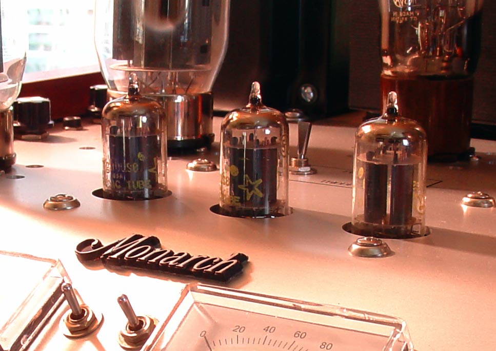
That also shows the mounting system I used, courtesy of the local hardware store. The standoffs come in various lengths and are already tapped at both ends for screws. Attach them loose to the chassis, attach the board to those, give it a wiggle to align everything, and tighten it up. The dress washers are nice because you can drill bigger locator holes to add the all important slop factor and without any rough edges showing. You can control the amount of tube sticking out the top by adjusting the standoff length - I wanted more of a concealed look and made sure the holes were big enough to get good chimney effect for cooling. Haven't smoked anything yet anyway.
PS ... No holes on mine for the bias pots as I I used remotely located rotary bias pots ... no mucking about with tiny screwdrivers for me!


Only mod to the VTA board should be installing the big caps on the other side of the board. Easy peasy because the board has solder pads on both sides.

That also shows the mounting system I used, courtesy of the local hardware store. The standoffs come in various lengths and are already tapped at both ends for screws. Attach them loose to the chassis, attach the board to those, give it a wiggle to align everything, and tighten it up. The dress washers are nice because you can drill bigger locator holes to add the all important slop factor and without any rough edges showing. You can control the amount of tube sticking out the top by adjusting the standoff length - I wanted more of a concealed look and made sure the holes were big enough to get good chimney effect for cooling. Haven't smoked anything yet anyway.
PS ... No holes on mine for the bias pots as I I used remotely located rotary bias pots ... no mucking about with tiny screwdrivers for me!

